NFS2-3030/E Installation Manual — P/N 52544:N1 07/18/2014 47
Fire/Security Applications Applications
• If the system has arming and disarming capability, a ringback signal from the Central Station to
the arming location is required. The ringback signal informs the Protected Premises Control
Panel that the signal to arm/disarm has been received by the Central Station.
• A single SLC loop may be used for both Fire and Security Device Connections.
There are five software type IDs associated with security operation: A
CCESS
M
ONITOR
alarm,
A
REA
M
ONITOR
, E
QUIP
M
ONITOR
, S
ECURITY
-L, and S
YS
M
ONITOR
. There is also one software
function, Security Delay (SDEL). These software elements are essential to all aspects of security
operation, including Control-By-Event (CBE) programming. Devices with the type IDs A
CCESS
M
ONITOR
and E
QUIP
M
ONITOR
do not automatically display at the LCD or require state change
acknowledgment. State changes in devices with these software types may be output at a printer.
Refer to this panel’s Programming manual for more information about the characteristics of
software type IDs.
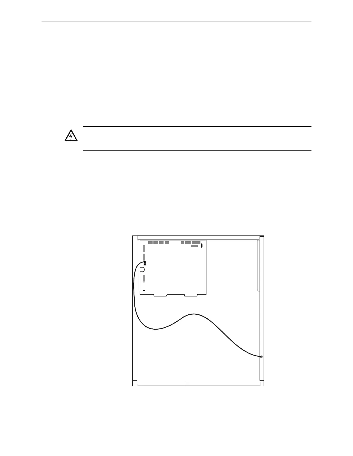
4.5.3 Installing a Security Tamper Switch
Follow the instructions below to wire the cabinet with a Security Tamper Switch kit model STS-1.
1. Install the STS-1 Tamper Switch onto the side of the backbox opposite the door hinge, pushing
the switch through the opening until it snaps into place.
2. Install the magnet on the same side of the cabinet door as the lock. Push the magnet through
the opening in the door until it snaps into place.
3. Connect the STS-1 connector to J6 Security on the CPU.
4. Program panel supervision for Tamper Input “Yes”.
WARNING:
XP TRANSPONDER CIRCUITS (XPP-1, XPM-8, XPC-8, XPR-8, XPM-8L) ARE NOT SUITABLE
FOR SECURITY APPLICATIONS.
3030-sts1.cdr
STS-1
mounting
location
(side opposite
of door hinges)
Connect to
J6 Security
Figure 4.5 Installing the STS-1 Security Tamper Switch