27
Instructions for the installer
Connection to the chimney
The chimney is indispensable for correct boiler operation; it must therefore comply with the following requirements:
• it must be made of waterproof material and be resistant to ue gas temperature and related condensate;
• it must have appropriate mechanical characteristics and low thermal conductivity;
• it must be perfectly sealed;
• it must be as vertical as possible and the roof terminal is to have a cap ensuring ecient and constant ue gas exhaustion;
• it must not be less wide than the boiler ue gas outlet diameter; squared or rectangular section chimneys must bear an internal section,
10% larger than the section connected to the boiler draught excluder device;
• starting from the boiler, the duct connecting to the chimney is to follow a vertical direction and must be long not less than twice its
diameter before joining the chimney.
≥ 1,5 m
Ø
Ø
2 Ø
2 Ø
≤ 1 m
≤ 1 m
≥ 3 %
≥ 3 %
≥ 1,5 m
> 3 Ø > 3 Ø
Fig. 6 Connections to the chimney of open chamber models
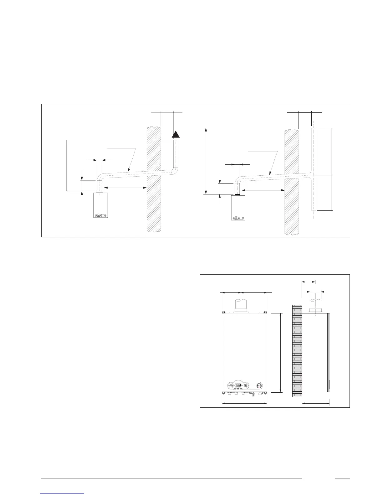
Direct emission into the atmosphere
Natural draught boilers can vent ue gas directly into the atmosphere
via a duct which goes through the outside walls of the building and
ends with an anti-wind gust device terminal.
The ue gas exhaust duct is to comply with the following
requirements:
• its sub-horizontal part inside the building must be as short as
possible (not longer than 1,000 mm);
• it is not to have more than 2 direction changes;
• it can host only one single boiler ue gas exhaust system;
• its section, which is passing through the wall is to be protected
by a sheath duct; the part of the sheath duct facing the inside of
the building is to be sealed, while the part facing outwards is to
be left open;
• its end section, on which the draught terminal is to installed, is to
protrude from the wall of the building for a length of a least twice
the diameter of the duct;
• the terminal must be no less than 1.5 meters above the connection
for the ue gas venting duct on the boiler.
400
700
250
Ø 130,8