2. Specification
— 2-6 —
2.2.3. CN6: Interface Connector
The CN6 connector interfaces with the CC-Link network.
The followings are the reference for the connectors that are used for the CN6 connector.
Table 2-4: CN6 mating connectors
Connector, Driver Unit side
Phoenix Contact Gmbh, & Co.
MSTB2,5/5-GF-5,08AU or
equivalent
Mating connector
Phoenix Contact Gmbh, & Co.
MSTB2,5/5-STF-5,08AU or
equivalent
Table 2-5 below shows the reference data for the mating connectors.
Table 2-5: Reference data of the mating connector
Item Specification
Cable to be used (single connection)
0.2 to 2.5 [mm
2
] (twisted) (AWG24 to 12)
Cable to be used (double connection)
0.2 to 1.5 [mm
2
] (twisted)
Removed coat length
7 [mm]
Machine screws to be used
M3
Tightning torque
0.5 to 0.6 [N·m]
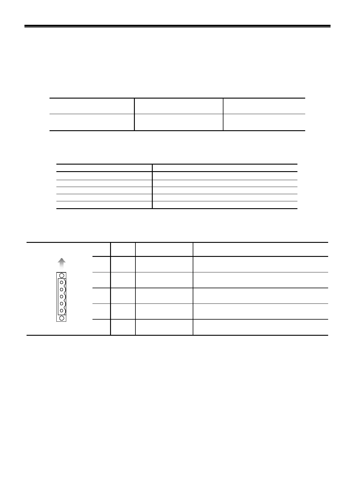
2.2.3.1. CN6 Pin-Out
Table 2-6: CN6 pin-out
Pin
No.
Signal
code
Function Description
1 FG
Frame ground Connect the frame ground
2 SLD
Shield Connect the shielded cable (Frame ground cable)
3 DA
Data A Connect the data A cable
4 DB
Data B Connect the data B cable
1: FG
Top of the Driver Unit
2: SLD
3: DA
4: DB
5:
DG
5 DG
Data ground Connect the data ground cable
 Loading...


