3. Operation
— 3-4 —
3.4. Monitoring Control Input/Output
The Monitor IO (Input/Output monitor) monitors the state of remote inputs and outputs of the
CN6 interface connector.
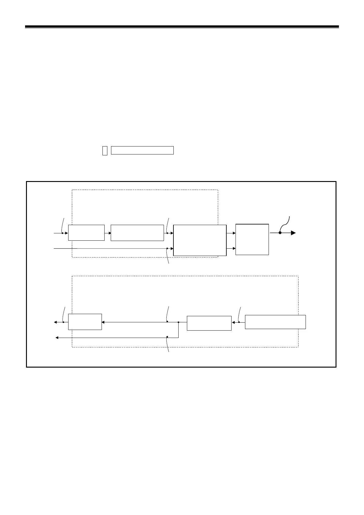
Figure 3-2 “Monitor of the control Input/Output functions and their state” below shows the
relation between the function of control inputs and outputs of the Driver Unit and the Monitor IO.
You can monitor the state of each part using Monitor IO0 to IO4 accordingly.
◊ This section describes the IO4, the monitor of Input/Output of the CC-Link and the BS, the
monitor of status of interface. Refer to “Appendix 1: Check of the Input/Output Signal” for
other monitors.
Besides the above way of monitoring, “ON and OFF” of each function can be monitored by
inputting
F+Control I/O Function .
Fig. 3-2: Monitor of the control I/O functions and their state
Command PI:Editing Input port (PI0 is fixed to EMST Input (Emergency stop).)
FN: Input function
AB: Input polarity
NW: Anti-chattering timer
Input function
AB: Input polarity
0: A
(Normally open)
1: B (Normally closed)
NW: Anti-chattering timer
0.0 to 1 000.0[ms]
CN2: Input
FN: Input function
EMST, ACLR,-----etc: Input
function
Monitor IO0 Monitor IO1
Monitor IO2,
Monitor F*** (*: Function name)
Command PO: Editing Output port (PO0 is set to the output DRDY(Driver Unit ready) or the output NRM(Normal)).
FN: Output function
GC: Output logic
ST: In-position stability timer
Output function
GC: Output logic
0: Positive logic
1: Negative logic
CN2: Output
Monitor IO0
Monitor IO3
Moitor F
*** (*
is a function name.)
CP: Control priority
CN6: Input
Monitor IO4
CN6:Output
Monitor IO1
Monitor IO4
FN: Output function
Output function: DRDY, WRN etc
ST: In-position stabilit
timer 0.0 to 1 000.0 [ms]

 Loading...

