2. Specification
— 2-9 —
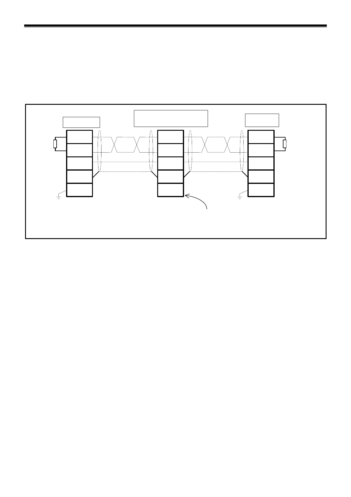
2.2.8. Wiring Example
Refer to “Figure 2-4: Wiring example” below for wiring the Drive Unit to the CC-Link.
◊ Be sure to use a cable dedicated to the CC-Link.
◊ The wiring order is not necessarily the same order of station numbers.
Fig. 2-4: Wiring example
DA
DB
DG
SLD
FG
DA
DB
DG
SLD
FG
DA
DB
DG
SLD
FG
Terminating
resistor
Terminating
resistor
CC-Link dedicated cable CC-Link dedicated cable
Master station
Remote station
(EDC Driver Unit)
Local station
When the EDC Driver
Unit is the terminating
unit, the SW4 switch
may be used for the
function of terminating
resistor.
When the grounding terminal of the Driver Unit (Heat sink) is
grounded, grounding of the FG terminal of the CN6 connector
is not necessary.
Connect the shielded wire of the CC-Link dedicated cable to the SLD terminal of CN6 connector.
The SLD terminal is connected to the housing of the Driver Unit through the FG terminal and
thus, the shielded wire is grounded through the gorunding terminal of the Driver Unit (Heatsink).
Connect the terminating resistor between the DA and DB terminal of the both end units of the
network .
◊ The SW4 switch sets the terminating resistor for the EDC Driver Unit.
 Loading...


