2. Specification
— 2-7 —
2.2.4. SW1•SW2: Station Number Switch
These rotary switches set the station number from 1 to 64.
The SW1sets the tens place of the number, while the SW2 switch sets the ones place.
Table 2-7: Station number switch
SW1 SW2 Station number
0 0 (Never set)
0 1 1 (Shipping set)
…
…
…
Driver U nit’s upper side
SW2: ×1
SW 1: × 10
5 0
1
2 3
4
6
7
8
9
5 0
1
2 3
4
6
7
8
9
6 4 64
2.2.5. SW3: Baud Rate Setting Switch
The switch sets the baud rate.
Table 2-8: Baud rate setting switch
SW3
Baud rate[bps]
0
156k
1
625k
2
2.5M
3
5M
4
10M (Shipping set)
5 0
1
2 3
4
6
7
8
9
Driver Unit’s u pper side
5 - 9
Never set
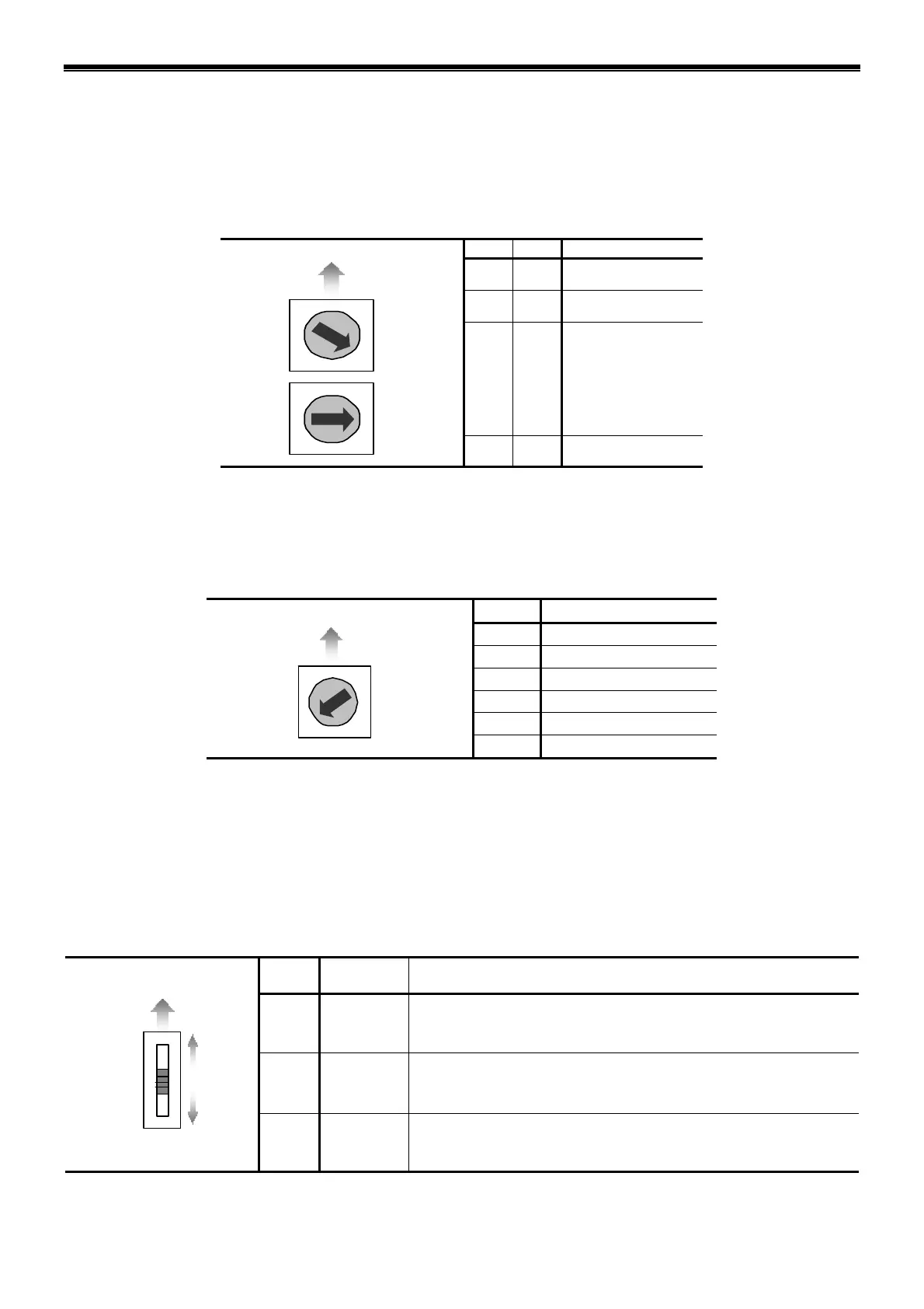
2.2.6. SW4: Terminal Resistor Switch
Set the terminal resistor when connecting the Driver Unit to the end of the network.
◊ Select the resistor value in accordance with the characteristic impedance of the cable.
Be sure to turn off the power of the Driver Unit when setting the terminal resistor.
Table 2-9: Terminal resistor setting switch
SW4
Terminating
resistance
Description
Up
130 [Ω]
• The terminal resistor is on
(When the characteristic impedance of the cable is 130 [Ω])
Neutral
None
• The terminal resistor is off (Shipping set)
Driver Unit’s upper side
130Ω
11 0Ω
FF
Down
110 [Ω]
• The terminal resistor is on
(When the characteristic impedance of the cable is 110 [Ω])

 Loading...

