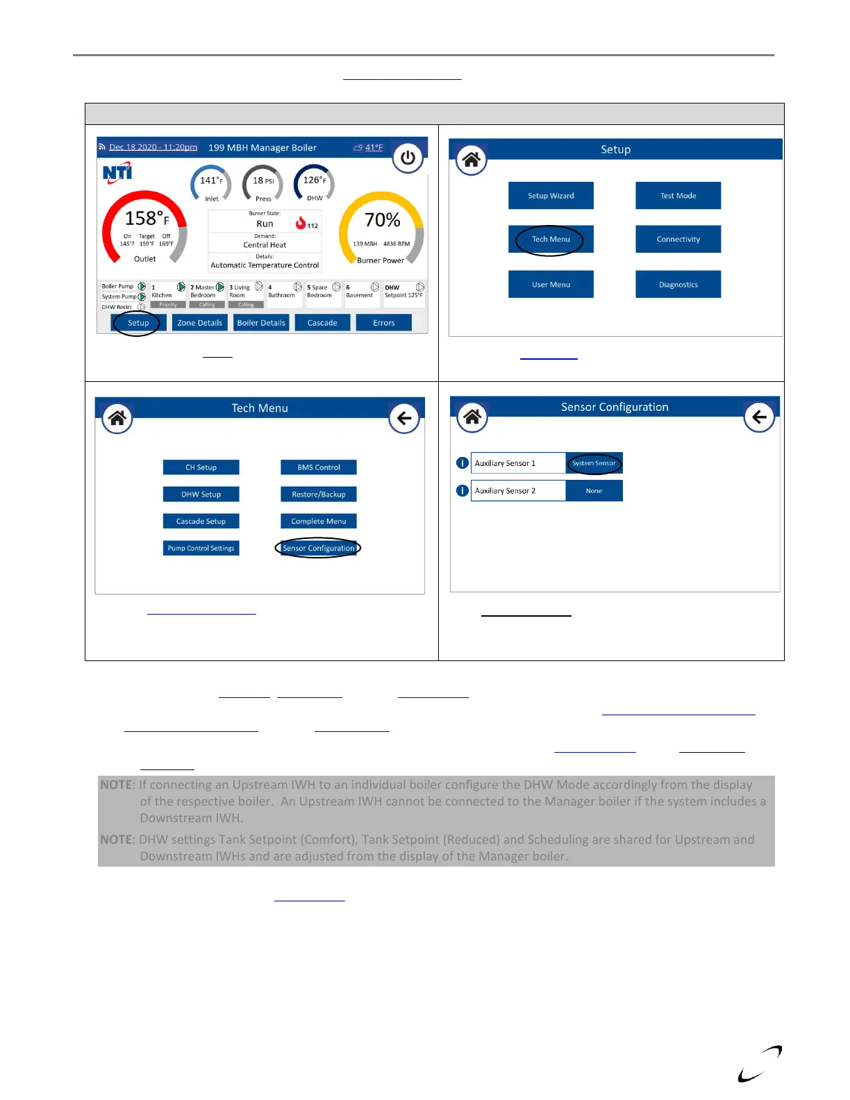
6. Configure System Sensor Input – from the Sensor Configuration menu of the Manager boiler, set Auxiliary Sensor 1 =
System Sensor; see Figure 11-5.
7. Configure Settings – CH Setup, DHW Setup and WiFi Connectivity are managed by the Cascade Manager and need to
be set from the Manager boiler’s touchscreen display via the typical menus; see sections 16.0 DISPLAY MENU GUIDE
and 17.0 WIFI CONNECTION. Use the Setup Wizard to have the display walk you through the setup procedure.
NOTE: If the cascade system is heating a Downstream IWH, it is necessary to set Cascade Setup option DHW Mode
(Cascade) = Downstream IWH (Tank Sensor or Aquastat) on the Manager boiler.
NOTE: If connecting an Upstream IWH to an individual boiler configure the DHW Mode accordingly from the display
of the respective boiler. An Upstream IWH cannot be connected to the Manager boiler if the system includes a
Downstream IWH.
NOTE: DHW settings Tank Setpoint (Comfort), Tank Setpoint (Reduced) and Scheduling are shared for Upstream and
Downstream IWHs and are adjusted from the display of the Manager boiler.
NOTE: If using an external signal (0-10V) for modulation control of the Cascade power or setpoint temperature, set
Control Mode from the BMS Control menu of the Manager boiler accordingly.
 Loading...