nVent RAYCHEM Elexant 4010i/4020i User Manual
RAYCHEM-AR-H60624-40X0iOpsManual-EN-1905 nVent.com
|
11
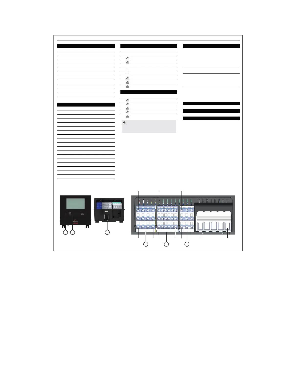
2.4 Connection and Indicators
CONNECTIONS AND INDICATORS
A. TB1 Wiring
Terminals Function
1 TS1 (White)
TS1 (Red)
TS1 (Red)
TS2 (White)
TS2 (Red)
TS2 (Red)
TS3 (White)
TS3 (Red)
TS3 (Red)
TS Lim (White)
TS Lim (Red)
TS Lim (Red)
2
3
4
5
6
7
8
9
10
11
12
B. TB2 Wiring
Terminals Function
1 TC3+
TC2+
TC1+
TC3–
TC2–
TC1–
– No Connect
SSR–
SSR+
DIGITAL INPUT (COM)
DIGITAL INPUT 1
DIGITAL INPUT 2
2
3
4
5
6
7
8
9
10
11
12
RS485 IN+
RS485 IN–
RS485 COM
RS485 OUT+
RS485 OUT–
13
14
15
16
17
E. Status LEDs
F. USB Connector
G. Ethernet Connection
H. Profibus (optional)
Status:
Indicates status of Elexant 4020i module
Off No power
Green Normal operation, no internal faults
Red Device Reset
Flash R/G Unlocked/Not Calibrated
COMM
Flash Green Receive Active
Alarm
Red Illuminates when an alarm is tripped
Flash Red Transmit Active
Output Shows status of switched output
C. TB3 Wiring
Terminals Function
1 24V+ OUT
Limiter Relay
Output Relay
24V COM
External Jumper Required
External Jumper Required
Alarm_NC
Alarm _COM
Alarm_NO
2
3
4
5
6
7
8
9
D. TB4 Wiring
Terminals Function
1 EGND
POWER IN (L1)
POWER IN (L2/N)
L1 ACV Sense
2
3
4
L2/N ACV Sense
5
WARNING: Shock Hazard.
Disconnect from live voltage prior
to accessing terminals
1 53 3 912
B
18
1 1
TB1 TB2 TB3
TB4
F
E
H
A
C
CONNECTIONS AND INDICATORS
A. TB1 Wiring
Terminals Function
1 TS1 (White)
TS1 (Red)
TS1 (Red)
TS2 (White)
TS2 (Red)
TS2 (Red)
TS3 (White)
TS3 (Red)
TS3 (Red)
TS Lim (White)
TS Lim (Red)
TS Lim (Red)
2
3
4
5
6
7
8
9
1
3
10
11
12
B. TB2 Wiring
Terminals Function
1 TC3+
TC2+
TC1+
TC3–
TC2–
TC1–
– No Connect
SSR–
SSR+
DIGITAL INPUT (COM)
DIGITAL INPUT 1
DIGITAL INPUT 2
2
3
4
5
6
7
8
9
10
11
12
RS485 IN+
RS485 IN–
RS485 COM
RS485 OUT+
RS485 OUT–
13
14
15
16
17
RS485 COM
18
E. Status LEDs
F. USB Connector
G. Ethernet Connection
H. Profibus (optional)
Status:
Indicates status of Elexant 4020i module
Off No power
Green Normal operation, no internal faults
Red Device Reset
Flash R/G Unlocked/Not Calibrated
COMM
Flash Green Receive Active
Alarm
Red Illuminates when an alarm is tripped
Flash Red Transmit Active
Output Shows status of switched output
C. TB3 Wiring
Terminals Function
1 24V+ OUT
Limiter Relay
Output Relay
24V COM
External Jumper Required
External Jumper Required
Alarm_NC
Alarm _COM
Alarm_NO
2
3
4
5
6
7
8
9
D. TB4 Wiring
Terminals Function
1 EGND
POWER IN (L1)
POWER IN (L2/N)
L1 ACV Sense
2
3
4
L2/N ACV Sense
5
WARNING: Shock Hazard.
Disconnect from live voltage prior
to accessing terminals
1 53 3 912
B
18
1 1
TB1 TB2 TB3
TB4
F
E
H
A
C
Figure 2 - Connections and Indicators
2.5 Mounting/Removal Procedures
2.5.1 Elexant 4010i mounting/removal procedure
2.5.2 Elexant 4020i mounting/removal procedure
2.5.2.1 Elexant 4020i mounting procedure
Insert the rear top of the module into the DIN rail, then push down and inwards to engage the clip.

 Loading...
