20 | nVent.com
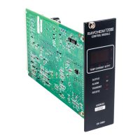
The control module will then begin to display the following three parameters in sequence:
• Actual measured temperature from the temperature sensor(s),
• Heat trace load current in amperes, and
• The CONTROL SETPOINT temperature.
As these three values are displayed (each for approximately 2.5 seconds in duration), a
corresponding LED immediately below the display area illuminates to indicate which parameter
is being shown. Under certain conditions, the control module will display several messages on
the three-character display in place of one of these three parameters (see Section 3.3).
3.2.3 ‘TEMP’ STATUS LED
The TEMP status LED is located below the left-most character of the control module’s front
panel display. When illuminated, this LED indicates that the present value being shown on the
display is the actual temperature of the designated control temperature sensor (as determined
by the TS CONTROL MODE setting).
3.2.4 ‘CURRENT’ STATUS LED
The CURRENT status LED is located below the middle character of the control module’s front
panel display. When illuminated, this LED indicates that the present value being shown on the
display is the actual heat trace load current in amperes. If this LED is flashing, then it indicates
that the control module has measured a ground fault current in excess of the GF TRIP
CURRENT or has encountered a severe overcurrent situation and has tripped the output off.
3.2.5 ‘SETPT’ STATUS LED
The SETPT status LED is located below the right-most character of the control module’s front
panel display. When illuminated, this LED indicates that the present value being shown on the
display is the present value of the CONTROL SETPOINT temperature setting.
3.2.6 ‘OUTPUT’ STATUS LED
The OUTPUT status LED is located below the SETPT status LED on the right side of the control
module’s front panel display. When illuminated steadily, this LED indicates that the output
switch (contactor or SSR) is on and is allowing current to flow into the heating circuit. If this
LED is flashing, it indicates that the control module is pulsing its output on and off to maintain
the CONTROL SETPOINT temperature and/or control the average amount of current/power
that the heating load uses (proportional control mode, SSR option only).
3.2.7 ‘ALARM’ STATUS LED
The ALARM status LED is located below the OUTPUT status LED on the right side of the
control module’s front panel display. The color of this LED is amber for the CM 2000+, and red
for the CM 2000. If the control module detects any alarm condition, this LED will flash at a rate
of once per second.
3.2.8 ‘TRANSMIT’ STATUS LED
The TRANSMIT status LED is located below the ALARM status LED on the right side of the
control module’s front panel display. This LED will flash whenever the control module sends
information over its communication port to either the AC 2000 or the AC 2000+ alarm/
communications interface card.
3.2.9 ‘RECEIVE’ STATUS LED
The RECEIVE status LED is located below the TRANSMIT status LED on the right side of the
control module’s front panel display. This LED will flash whenever the control module receives
information over its communication port from either the AC 2000 or the AC 2000+ alarm/
communications interface card.

 Loading...