6 | nVent.com
SECTION 1 OVERVIEW
1.1 INTRODUCTION
This manual provides information pertaining to the installation, operation, testing, adjustment,
and maintenance of all the components of the RAYCHEM T2000 Series Heat Tracing
Controller (HTC). A RAYCHEM T2000 HTC is made up of at least one card rack, one alarm/
communications interface card, and one or more control modules, each with its own current
transformer and switching module.
The information coincides with the specific releases of firmware for the CM 2000, CM 2000+
and the AC 2000+ components which are listed on the cover page. As nVent releases new
firmware to significantly modify or enhance any of these components, new documentation
will accompany these releases. To ensure that you are using the correct documentation
for your particular version of RAYCHEM T2000 HTC, compare the firmware version number
of each component against the version numbers listed on the front page of this manual.
Assubsequentchangesaremade,supplementstothisdocumentwillbeincludedinmanuals
shipped after the firmware is released. Supplements will make specific reference to the
operational or functional changes.
Additional copies of this manual may be downloaded from the Literature section of
nVent.com.
1.2 RAYCHEM T2000 COMPONENTS
The RAYCHEM T2000 HTC is made up of a number of modular components, allowing the
ultimate in design flexibility. Figure 1-1 shows the RAYCHEM T2000 HTC with all of its
components. Appendix A lists the specifications for all of these components.
Flexible switch and wiring configurations allow the RAYCHEM T2000 HTC to be used in most
heat tracing applications. Please contact your nearest nVent sales office to discuss your
requirements. The following sections describe the primary function of each component.
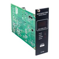
1.2.1 CM 2000 CONTROL MODULE
The CM 2000 control module is the original control module used in the RAYCHEM T2000
system and has been replaced by the CM 2000+. Firmware versions will range from versions
V2.30 to V2.35. The CM 2000 control module is designed to provide all heat tracing control and
monitoring functions for a single heating circuit. It easily inserts into any of the four types of
card racks.
1.2.2 CM 2000+ CONTROL MODULE
The CM 2000+ control module is an enhanced version of the original CM 2000 control module.
Firmware versions will range from V3.14 and higher. The CM 2000+ control module is designed
to provide all heat tracing control and monitoring functions for a single heating circuit. It is
compatible with any of the four types of card racks.
1.2.3 AC 2000 ALARM/COMMUNICATIONS INTERFACE CARD
The AC 2000 is the original alarm/communications interface card designed for use with
the RAYCHEM T2000 system. As it is purely a hardware device and does not include a
microprocessor, it contains no firmware. The AC 2000 is designed to provide a modem
communications interface between the control modules and an external programming device
(780/GCC-9000, 760/HHP-9000, or 761 PMP).
One AC 2000 can act as the communications interface for up to 40 control modules. There
are four LEDs on the front panel of the AC 2000 that indicate communication activity between
the AC 2000 and any control module. There is also a single ALARM LED on the front panel to
indicate the status of the AC 2000’s internal alarm relay. This dry contact alarm relay (0.5 A
Max. 240 VAC Max.) is for remote alarm indication. It provides both a “fail-safe” normally open
and a “fail-safe” normally closed set of contacts. These normal states are true if the AC 2000 is
powered up and no alarms are present on any of the control modules (i.e.: the ALARM LED on
the front panel of the AC 2000 is off).
The AC 2000 will only operate when inserted into the left-most slot of the card rack.
However, the alarm relay connections are not available when using the CR 2000+ or the
CR 2000-CPS+ card racks.
See Appendix B4 for details on wiring to an AC 2000 alarm/communications interface card.

 Loading...