nVent.com | 19
SECTION 3 CONTROL MODULE PROGRAMMING AND CONFIGURATION
3.1 INTRODUCTION AND INITIAL POWER-UP
Section 3 provides complete operating and programming details for the CM 2000 and the
CM 2000+ control modules. These details consist of initial power-up information, front panel
features, and function descriptions including: purpose, valid range settings, the procedure for
use, and some operational tips and suggestions.
3.1.1 RANDOM START-UP DELAY
All CM 2000 and CM 2000+ control modules incorporate a random start-up delay feature,
ensuring that all units do not power on their load the same time. When power is first applied to
a control module, it will hold its output off for a random time (0 to 9 seconds), equal to the last
digit of the address displayed on the front panel of the control module. Once this start-up delay
has timed out, the control module will begin normal operation.
3.1.2 POWER-UP OUTPUT ENABLING
When power is applied to a CM 2000 control module it will always turn its output on for approx.
6 seconds if the load shedding mode is disabled. When power is applied to a CM 2000+ control
module it will only turn its output on for approx. 10 seconds if the auto-cycling feature has
been enabled and if the control module is not in load shedding mode. By momentarily turning
the control module’s output on at power-up, the integrity of the heating circuit is tested and any
faults will be detected immediately.
3.1.3 AUTO COMMUNICATIONS DATA RATE SELECTION (CM 2000+ ONLY)
All CM 2000+ control modules will support either low or high speed data communications
to allow their use in either existing (low speed) systems or new (high speed) installations.
TheCM2000+willautomaticallysetitscommunicationsdataratetoeither300or9600baud.
This selection is based on the data rate of the first l communication detected by the CM 2000+
after it is reset. All control modules sharing a common communication bus must communicate
at the same data rate. To disable this feature, install the E6 jumper on the CM 2000+ module.
By doing this, the CM 2000+ will only communicate at 300 baud.
3.2 FRONT PANEL FEATURES
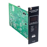
Front panel features of the control module are described in Figure 3-1. This figure contains
a detailed description of the indicators and label information. The remainder of this section
describes in detail the front panel display and status LEDs.
3.2.1 CONTROL MODULE FRONT PANEL DISPLAY
The three-character (seven segment plus decimal LED) display is found near the top of
the front panel of the CM 2000/CM 2000+ control modules. It is used to indicate certain
quantitative values to the operator. This display shows measured temperature and setpoint
values in °F or °C as well as actual load current in amperes. When the three-character display is
displaying a temperature value, either the °F LED or °C LED on right hand side of the display will
be illuminated depending on temperature units selected by the operator. Also, when displaying
temperature values in °F, the decimal point for the right-most character will also be illuminated.
3.2.2 DISPLAY OPERATION
All CM 2000 and CM 2000+ control modules have a random start-up delay associated with
them as described in Section 3.1.1. When power is first applied to a control module, it will
display the start-up delay (in seconds) and count down to zero. Immediately after this count
down has completed, the control module briefly (approximately 1/10 of a second in duration)
displays the version number of its operational program (firmware). This allows the user to refer
to specific Sections of the documentation as they relate to functions for a particular version of
the control module.
The control module then turns on all LEDs (except TRANSMIT and RECEIVE LEDs for the
CM 2000) and sequences through a test pattern so that the operator can verify that all LEDs
and display segments are functioning.

 Loading...