Display
NVIDIA Jetson TX2 NX DG-10141-001_v1.1 | 42
Parameter Requirement Units Notes
Trace at Component Region
Value 100 Ω ± 10%
Location At component region (Microstrip)
Trace entering the SMT pad One 45° See Figure 7-18
Trace between components Uncoupled structure See Figure 7-19
HDMI connector
Connector voiding
Voiding the ground below the signal lanes
0.1448(5.7mil) larger than the pin itself
See Figure 7-20
General: See Chapter 15 for guidelines related to Serpentine routing, routing over voids and noise coupling
Notes:
1. Longer trace lengths may be possible if the total trace loss is equal to or better than the target. If the loss is greater, the max
trace lengths will need to be reduced.
2. The average of the differential signals is used for length matching.
3. Do not perform length matching within breakout region. Recommend doing trace length matching to <1ps before vias or any
discontinuity to minimize common mode conversion.
4. If routing includes a flex or 2nd PCB, the max trace delay and skew calculations must include all the PCBs/flex routing.
Solutions with flex/2nd PCB may not achieve maximum frequency operation.
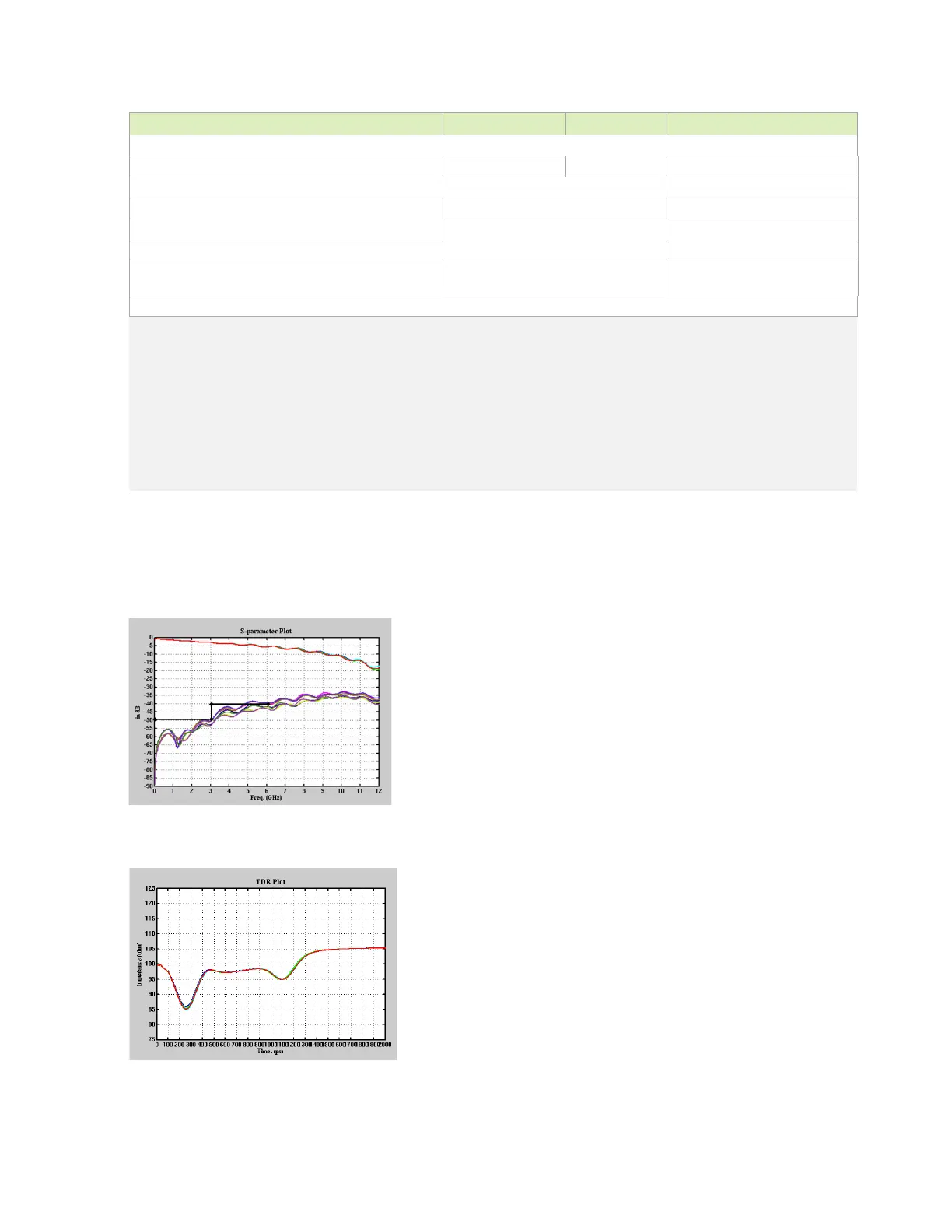
The following figures show the HDMI interface signal routing requirements.
Figure 7-9. IL and FEXT Plot
Figure 7-10. TDR Plot