Chapter 2
Board layout and settings
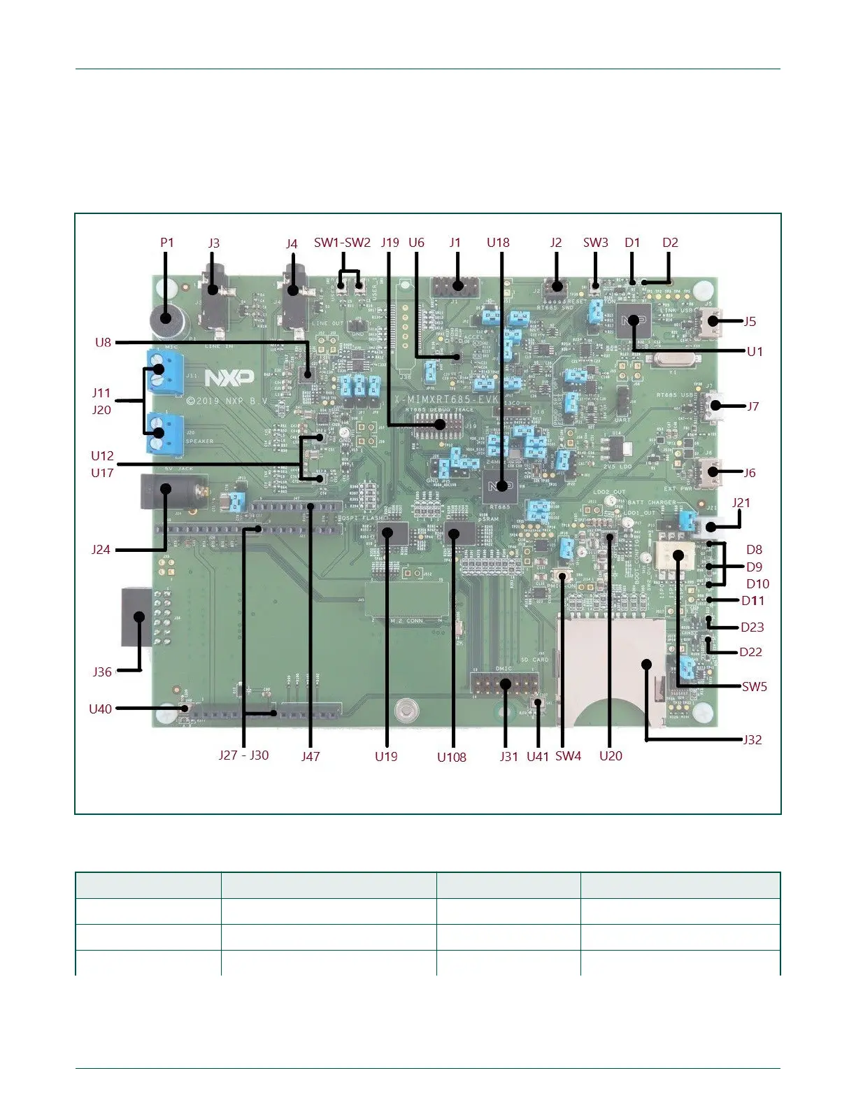
Figure 2 shows the layout of the board (top side), indicating location of the connectors and buttons.
Figure 2. i.MX RT685 EVK connectors, LEDs, buttons and headers
Table 1 provides a description of connectors, LEDs and buttons.
Table 1. Connectors, LEDs, buttons and headers
Circuit ref (Rev E) Description Default Reference
D1 Reset LED N/A Schematic
D2 Link2 boot LED N/A Schematic
D8 - D10 User LEDs. N/A User LEDS
Table continues on the next page...
NXP Semiconductors
i.MX RT685 Evaluation Board, Rev. 0, March 20 2020
User's Guide 5 / 31
 Loading...


