- 16 -
CSB
Instructions for installation and use
EN
The CSB control unit has been developed to control automatic single-phase barriers.
1. INTRODUCTION
3. TECHNICAL SPECIFICATIONS
2. MAIN CHARACTERISTICS
- Microprocessor logic
- LEDs displaying input status
- Integrated radio receiver 433Mhz 2 channels, 2048 codes
- Plug-in radio connector (not installed)
- 2-digit display
- Confi gurable outputs
- DOMINO connector
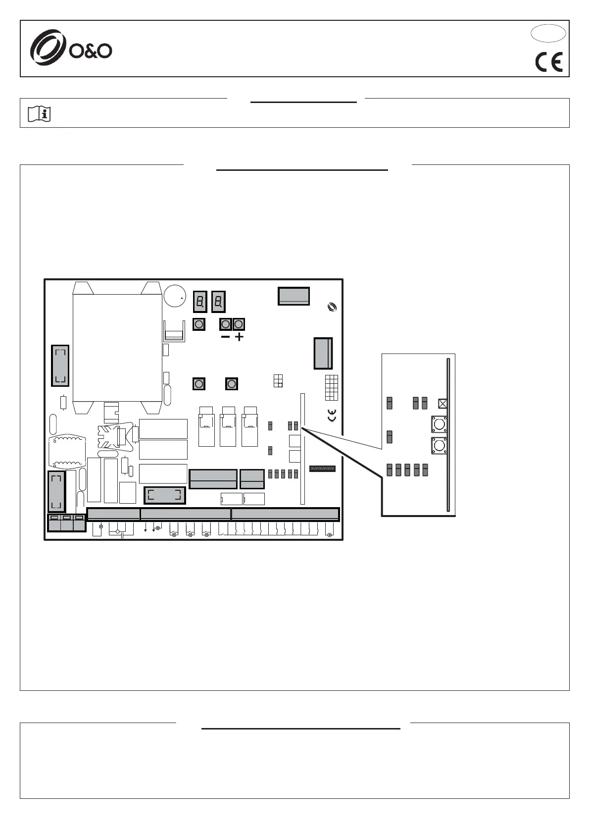
J1: 230Vac terminal board
J2: Flashing light/motor terminal block
J3: Plug-in radio connector (not installed)
J4: Outputs/accessories power supply terminal block
J5: Expansion module
J6: Antenna/Inputs terminal block
J7: Reverser terminal block
J9: Inverter plug-in (only for CSB-SP/XT)
- Power supply: 230Vac ±10%, 50/60Hz
- Motor output (only for CSB-BR): 230Vac; 3A max
- Traffi c light: 230Vac; 40W
- Accessory output: 24Vac; 1A max
J10: DOMINO connector
DL: 2-digit display
SW1: “START” control button
SW2: “PDM” control button
F1: Accessories and outputs fuse: 5x20 1A T
F2: Line fuse: 5x20 6.3A F
F3: Low voltage fuse: 5x20 250mA T
F,+,-: Programming push buttons
ANT
SHIELD
FCC
FCA
GGFM MA
AL
2345
2011
ONSO
COM
8k2
STOP
FTC
COM
CLOSE
OPEN
PDM
STAR T
OUT4
2nd
CH
RX
OUT4
OUT3
OUT3
OUT2
OUT2
OUT1
COND
24 Vac
MOTB
COM
MOT A
SL
SL COM
L
J8
NE
COM
SGN
12V
GND
AN
WD
REV
SGM
24V
F3
J10
F2
F1
J2
J1
J4
J9
SW1 SW2
J5
J7
J3
J6
F
DL
LED
FCC
FCA
STOP
CLOSE
OPEN
PDM
START
ENC
FTC