- 23 -
In the case of standard installations where no advanced functions are required, it is possible to proceed to
manual storage of the transmitters, making reference to programming table A and to the example for basic
programming.
1) If you wish the transmitter to activate output 1, press pushbutton PR1, otherwise if you wish the
transmitter to activate output 2, press pushbutton PR2.
2) When LED DL1 starts blinking, press hidden key on the transmitter, LED DL1 will remain continuously lit.
3) Press the key of the transmitter to be memorized, LED DL1 will fl ash quickly to indicate that it has been
memorized successfully. Flashing as normal will then be resumed.
4) To memorize another transmitter, repeat steps 2) and 3).
5) To exit memorizing mode, wait for the LED to go off completely or press the key of a remote control that
has just been memorized.
IMPORTANT NOTE: ATTACH THE ADHESIVE KEY LABEL TO THE FIRST MEMORISED TRANSMITTER
(MASTER).
In the case of manual programming, the fi rst transmitter assigns the key code to the receiver; this code is
necessary in order to carry out subsequent cloning of the radio transmitters.
7.4 MANUAL PROGRAMMING
7. RADIO RECEIVER
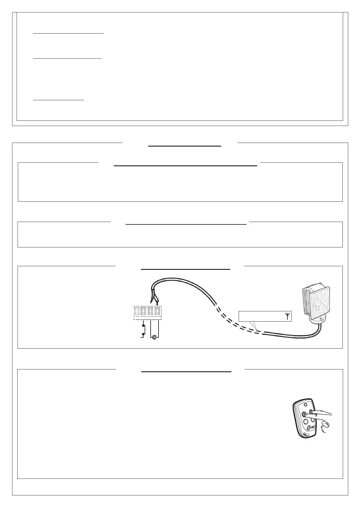
antenna cable RG58
7.1 RECEIVER TECHNICAL SPECIFICATIONS
- Max. n° of radio transmitters that can be memorized: 2048
- Frequency: 433.92MHz
- Code by means of: Rolling-code algorithm
- N° of combinations: 4 billion
7.2 RADIO CHANNEL FUNCTIONALITY
Channel 1: Start command
Channel 2: Closes the relay contact on the terminal block J4 “2nd CH RX”
7.3 ANTENNA INSTALLATION
Use an antenna tuned to 433MHz.
Connect the tuned antenna to the
antenna terminals using RG58 coaxial
cable.
SHIELD
ANT
FCC
J6
Hidden key
Description of level 3 parameters
·
, , :Output polarity
· Output polarity: The outputs can be confi gured as N.O. or N.C. but, in the event of a blackout the contacts open anyway.
·
:Velocity selection input
By enabling this parameter bar speed can be adjusted via the PDM input.
If the PDM is activated and parameter enabled the barrier moves at a speed equal to 60% of maximum speed, both when
opening and closing.
If the PDM input is not active, the barrier moves at the speed set in parameter and .
·
:Advanced setup
This parameter enables the use of special confi gurations to cater for specifi c necessities.
*=1 With this confi guration, the open command is recognised at on state, not at the signal front.