3. ENGINE
3-
Connecting Rod/Piston Pin Clearance
Using synthetic abrasive woven, clean piston pin
from deposits .
Inspect piston pin for scoring, cracking or other
damages.
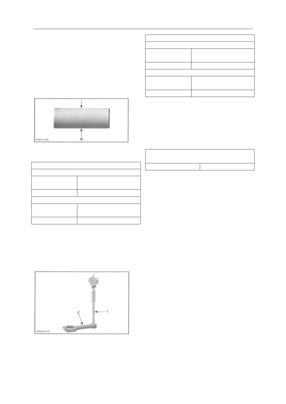
Measure piston pin . See the following illustration
for the proper measurement positions.
A. Piston pin diameter
19.996mm to20.000 mm
(.7872in to.7874in)
21.996mm to22.000 mm
(.866in to.8661 in)
Replace piston pin if diameter is out of
specifications.
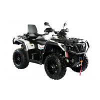
Measure inside diameter of connecting rod small
end bushing .
1. Bore gauge
2. Connecting rod
CONNECTING ROD SMALL END DIAMETER
20.010 mm to20.020 mm
(.7878in to.7882in)
20.010 mm to20.020 mm
(.7878in to.7882in)
Replace connecting rod if diameter of connecting
rod sma1l end is out of specifications. Refer to
BOTTOM END subsection for removal procedure.
Compare measurements to obtain the connecting
rod/piston pin clearance.
CONNECTING ROD/
PISTON PIN CLEARANCE
Piston Installation
For installation, reverse the removal procedure.
Pay attention to the following details.
Apply engine oi1 on the piston pin.
1nsert piston pin into piston and connecting rod.
For each cylinder, Install piston with the punched
arrow on piston dome is pointing toward the rear
side of the engine.
Front cylinder: Mark on top of piston must show
to intake side.
Rear cylinder: Mark on top of piston must show
to exhaust side.