---------APPENDIX
C
INTERFACE
CABLE
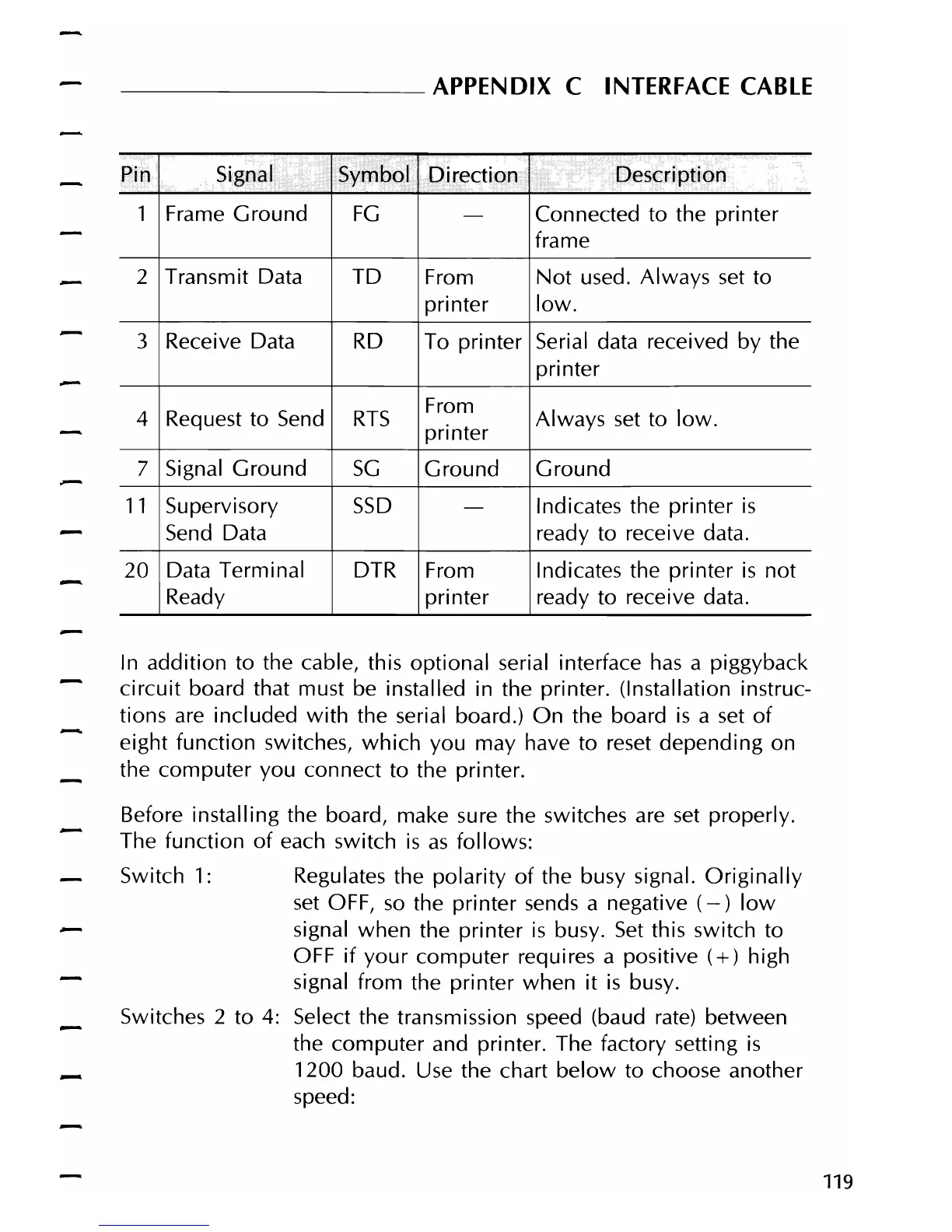
Pin Signal Symbol
Direction
Description
1 Frame Ground
FG
-
Connected to the printer
frame
2
Transmit Data
TD
From
Not
used. Always
set
to
printer
low.
3
Receive Data
RD
To printer Serial data received by the
printer
4 Request to
Send
RTS
From
printer
Always
set
to
low.
7 Signal Ground
SG
Ground Ground
11
Supervisory
SSD
-
Indicates the printer
is
Send
Data ready to receive data.
20
Data Terminal DTR
From
Indicates the printer
is
not
Ready printer ready to receive data.
In
addition to the cable, this optional serial interface
has
a piggyback
circuit
board that must be installed in the printer. (Installation instruc-
tions are included
with
the serial board.)
On
the board
is
a
set
of
eight function switches,
which
you may have to reset depending on
the computer you connect to the printer.
Before installing the board, make sure the switches are
set
properly.
The function
of
each switch
is
as
follows:
Switch
1:
Regulates the polarity
of
the busy signal.
Originally
set
OFF,
so
the printer sends a negative
(-)
low
signal when the printer
is
busy.
Set
this switch to
OFF
if
your
computer requires a positive
(+)
high
signal from the printer when
it
is
busy.
Switches 2 to 4: Select the transmission speed (baud
rate)
between
the computer and printer. The factory setting
is
1200 baud. Use the chart
below
to choose another
speed:
119