DIP switches
(ON = 1; OFF = 0)
DIP switches
(ON = 1; OFF = 0)
Table 5: Addressing table (address depends on the position of the switches)
Remarks:
■ The physical address of a module (1 to 32 max) must be identical to the
registered address via COM 32 software configuration.
■ When a module has to be replaced, all DIP switches must be configured as
the previous module.
■ Switch #6 (FRAME FILLING/REMPLISS TRAME) must be set to OFF and switch
#7 (DELAY/TEMPORISATION) must be set to ON (options unused).
■ The 8 analog input module systematically monopolizes 8 addresses.
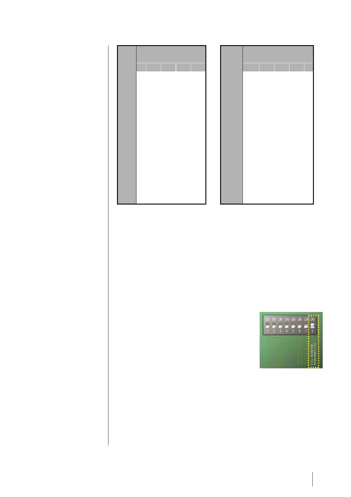
End Of Line Resistor
For the last module only of each line,
set switch #8 (EOL RESISTOR/RESISTANCE
F.D.L.) to ON or set the jumper of the
Analog Input Module to Closed (Figure
19: 8 Analog Input ModuleN).
Figure 13: End Of Line Resistor is set
to ON