The dry relay contacts (nominal resistive load of 5A at 250Vac or 30Vdc) are
identified as R1, R2, R3, R4 (Figure 27, tag A) and Fault (Figure 27, tag B).
Figure 27: Internal alarm relays (A) and fault relay (B) terminals
The relay contacts are represented when no power applies to the MX
32. The relays are programmed via the COM 32 application and can be
set as energized or de-energized.
Remote Acknowledgement Connector
If necessary, connect the ACQUIT (dry contact relay, NC) terminal to a remote
acknowledgement system.
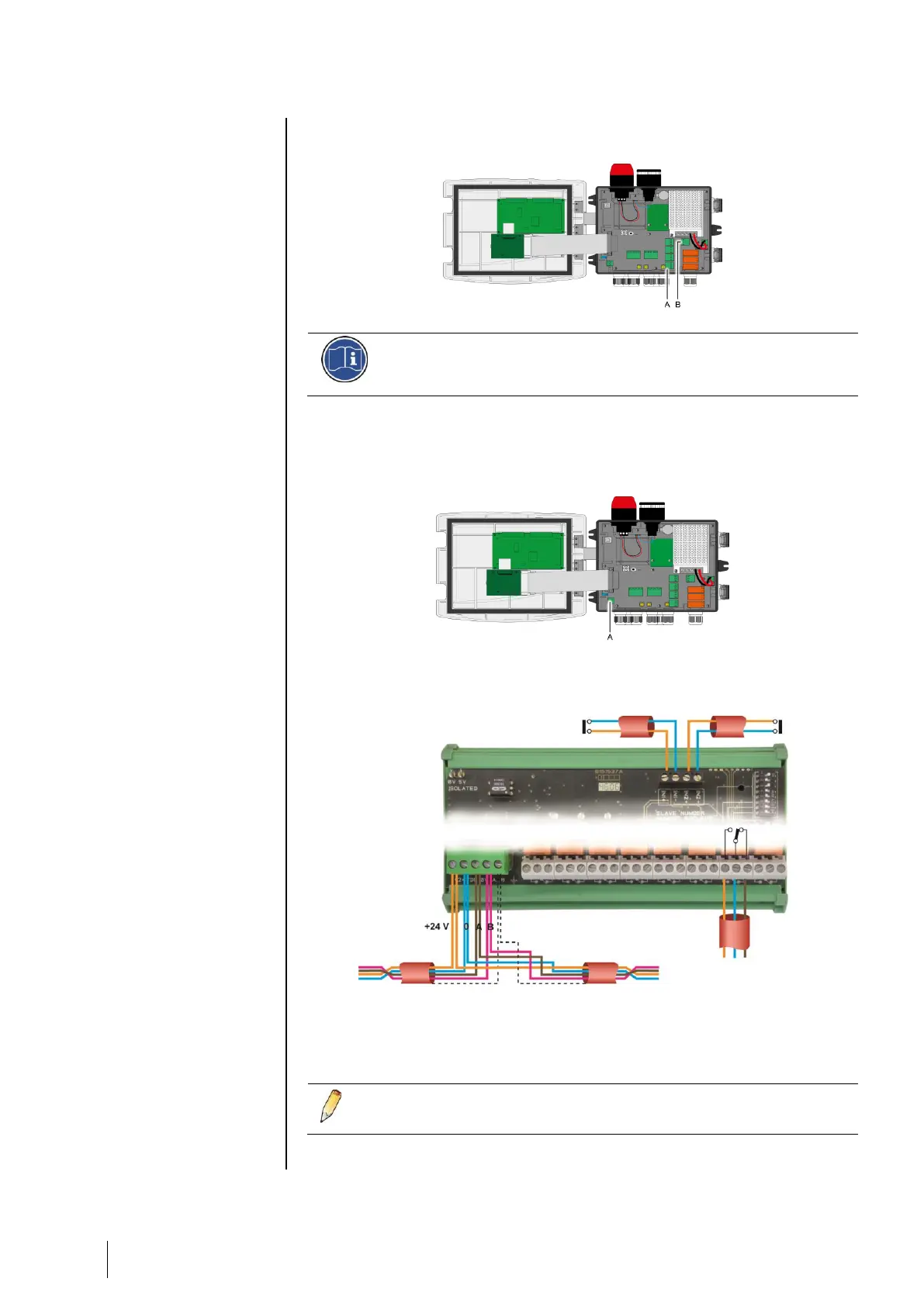
Figure 28: Remote acknowledgement connection (A).
4- or 8-Relay Modules
Figure 29: 4- or 8-relay module connections
If this module is the last on the line, do not forget to set the
switch marked EOL resistor/resistance FDL to ON.
To MX 32
or previous module
4 or 8 output contacts DPCO
(2A/250Vac-24Vdc