6 – Wiring and Electrical Connections
Chapter 6 │Wiring and Electrical Connections
This chapter details the electrical connections of all components of the system
(MX 32, modules, additional equipment).
Controller Connection
The electrical connections must be carried out by qualified personnel in
compliance with the different directives in force in the country of installation.
The MX 32 does not have a start/stop switch.
Certain voltage levels are capable of causing serious injuries or
even death. It is advised to install the material and cabling before
applying live voltage.
Since an incorrect or poor installation may cause measurement
errors or system failures, it is necessary to strictly follow all the
instructions in this manual in order to guarantee the proper
operation of the system.
Certified strain relief bushing required. Utilized cords shall comply
with all certified bushing specifications.
Suitable external cords shall be used in the end application and
shall be according to local rules/standards for MX 32 product.
Cables with an operating temperature of 70°C minimum (158 °F)
must be used because the temperature inside the controller can
reach 70°C (158 °F).
Access to terminal blocks
After unlocking the two toggle latches, swing the front cover towards the left in
order to access the wiring terminal.
100-240Vac Power Supply
The MX 32 can be powered from a 100-240Vac source at 50/60 Hz, 1.5A
max. Check the nature of the current and the voltage value prior to any
connection. The electrical connections must be carried when power is down.
A bipolar differential circuit breaker, 4A, type D, must be included in the
installation as means for disconnection. It must be suitably located and easily
reached and must be marked as the disconnecting device for the MX 32.
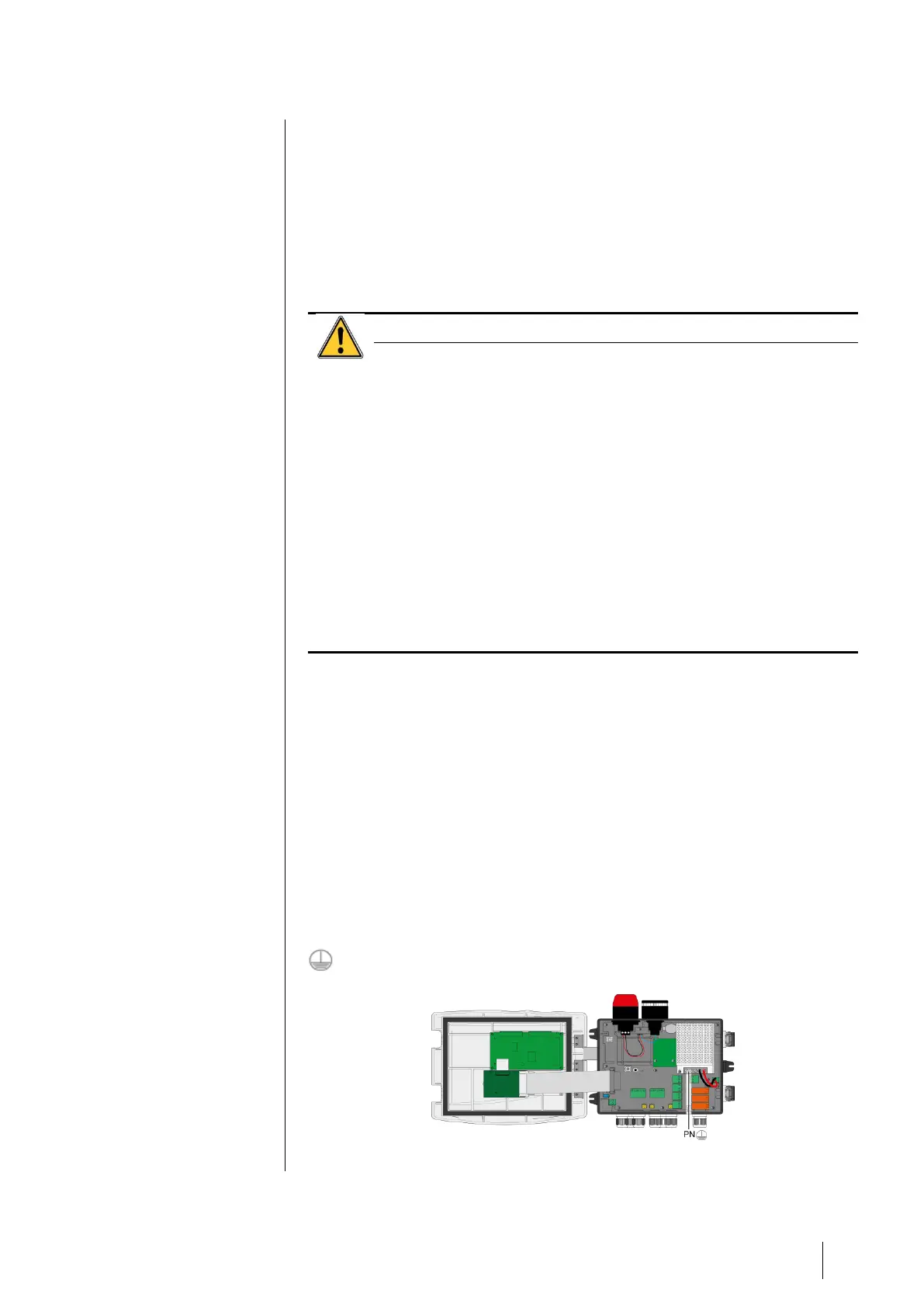
The main power shall be connected to the terminal block as indicated in
Figure 22. The ground conductor shall be connected to the ground terminal
fffff . Connect earth before connecting L/N conductors. Disconnect earth after
disconnecting L/N conductors.
Figure 22: Connection of the main power supply