RS485 Transmission
General Topology of RS 485 Network
The digital modules are linked by a two twisted pair shielded cable (4 x 0.22
m² minimum, MPI-22A type, nominal impedance 100 Ohms). This cable
carries the RS485 signal (A and B) on one pair and the power supply (24Vdc)
on the other pair. Shielding continuity must imperatively be carried out
between all the modules and the MX 32 controller.
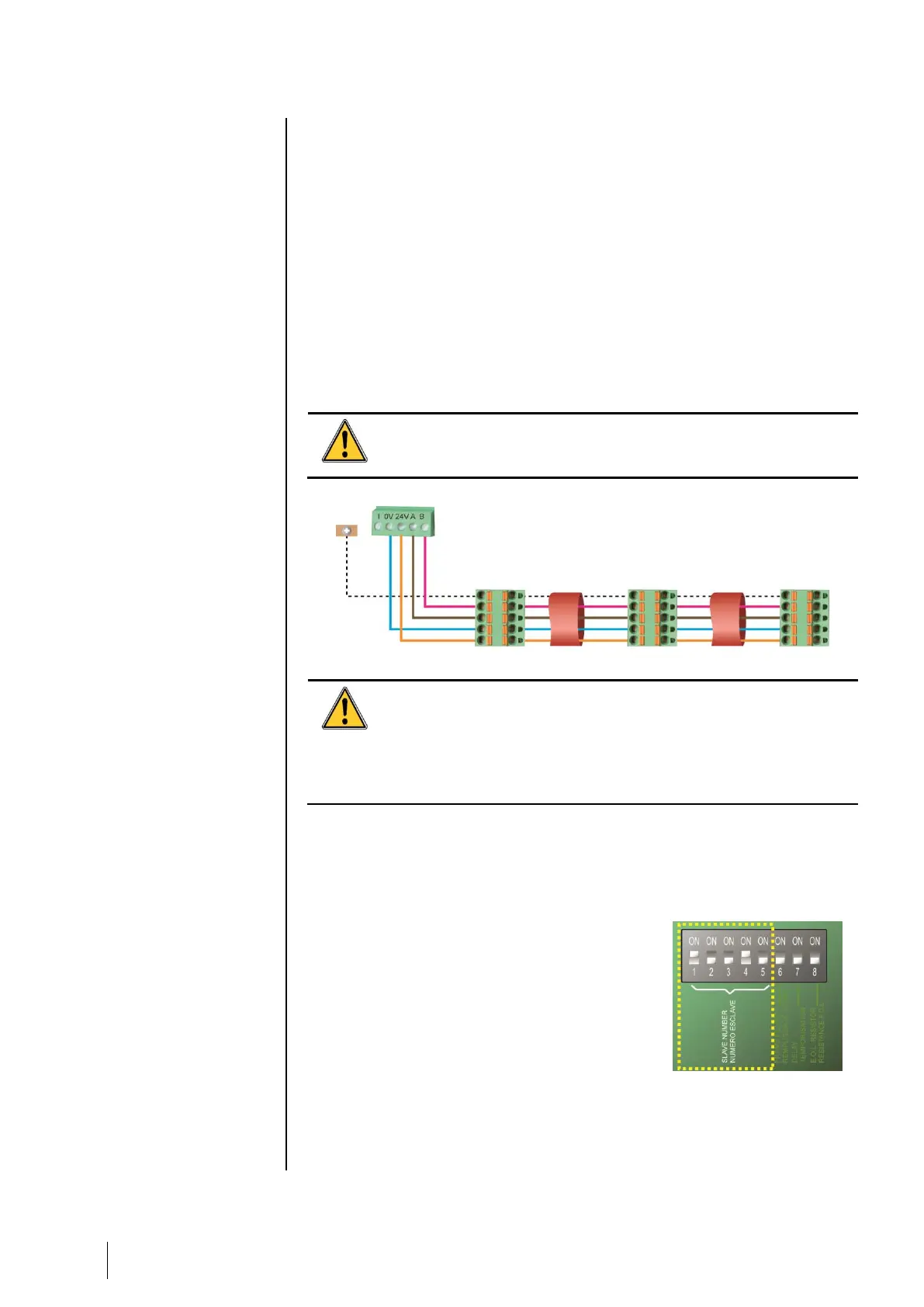
+ 24Vdc, 0V, A, B terminals are respectively connected to +24Vdc, 0V, A, B
terminals of the other modules and then to the terminal of the corresponding
line on the controller. The cable shield must be connected to the MX 32
ground terminal.
The 120-Ohm end of line resistor (EOL RESISTOR/RESISTANCE F.D.L) must be
activated on the last module present on the bus (whatever the last module).
No bare wire should remain apparent. For protection against
electromagnetic interference, the shield (or braid) should be cut
as short as possible and necessarily connected.
Figure 11: Connection of the modules on a line
The incorrect installation of the cables or cable glands can cause
measurement error or system malfunction.
Do not run the cables close to equipment such as engines,
transformers, or electrical lines generating a strong magnetic
field. It is always recommended to ensure a good separation
between these cables and the cables of other circuits.
Communication Setup
Module Address
All digital modules must be identified by a
unique address.
On all modules, DIP switches #1 to #5 allow to
set the address in binary mode.
In the illustration to the right, address 9 (10010)
has been defined.
The Addressing Table below lists the possible
combinations.
Figure 12: DIP switches for
address configuration
Terminal (detector,
module)