Relay modules
Function
This digital module, available in two
versions, allows for the management of:
■ 1 to 4 relay outputs;
■ or 1 to 8 relays.
In addition, it has 2 logic inputs.
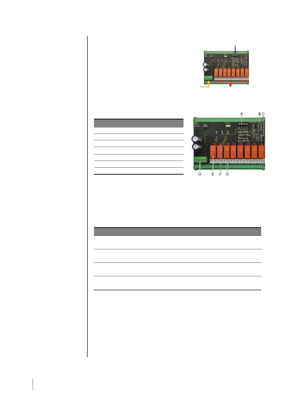
Figure 14: 8 relay module
Introduction
DIP switches for module configuration
DIP switches for relays configuration
Power supply and RS485 network
Programmable relays (4 or 8)
Relay status visual indicators
Figure 15: 8 relay module
A – Logic input terminals
Each of these two terminals may be connected to a voltage-free contact as
per Figure 29.
B – Module configuration DIP switches
These DIP switches are set according to the following table.
Slave number
Numéro esclave
See details in the paragraph Module Address on page 18.
Frame filling
Remplissage de trame
Factory settings. Do not modify.
Factory settings. Do not modify.
E.O.L Resistor
Résistance F.D.L.
See details in paragraph End of line Resistor, on page 19.
Table 6: Relay module configuration DIP switches
C – Relay configuration DIP switches
The DIP switches allow to choose between normally energized relay (the coil
is energized when not in alarm) or normally de-energized relay (the coil is
energized when in alarm). Set the switch to ON for energized relay or OFF for
de-energized relay. Each switch drives the relay having the same number
(switch #1 acts on relay #1). The contacts are represented with the module
not powered.
Re the 4 relay module, only switches #1 to #4 are active.