4-Analog Output Module
Function
This digital module delivers 1 to 4
discrete opto-isolated analog outputs
deactivated. Several detectors can be
assigned to one output allowing the
management of the lowest, highest
and averaged value. When non
configured, the analog output is set to
0mA. The module also features two
logic inputs.
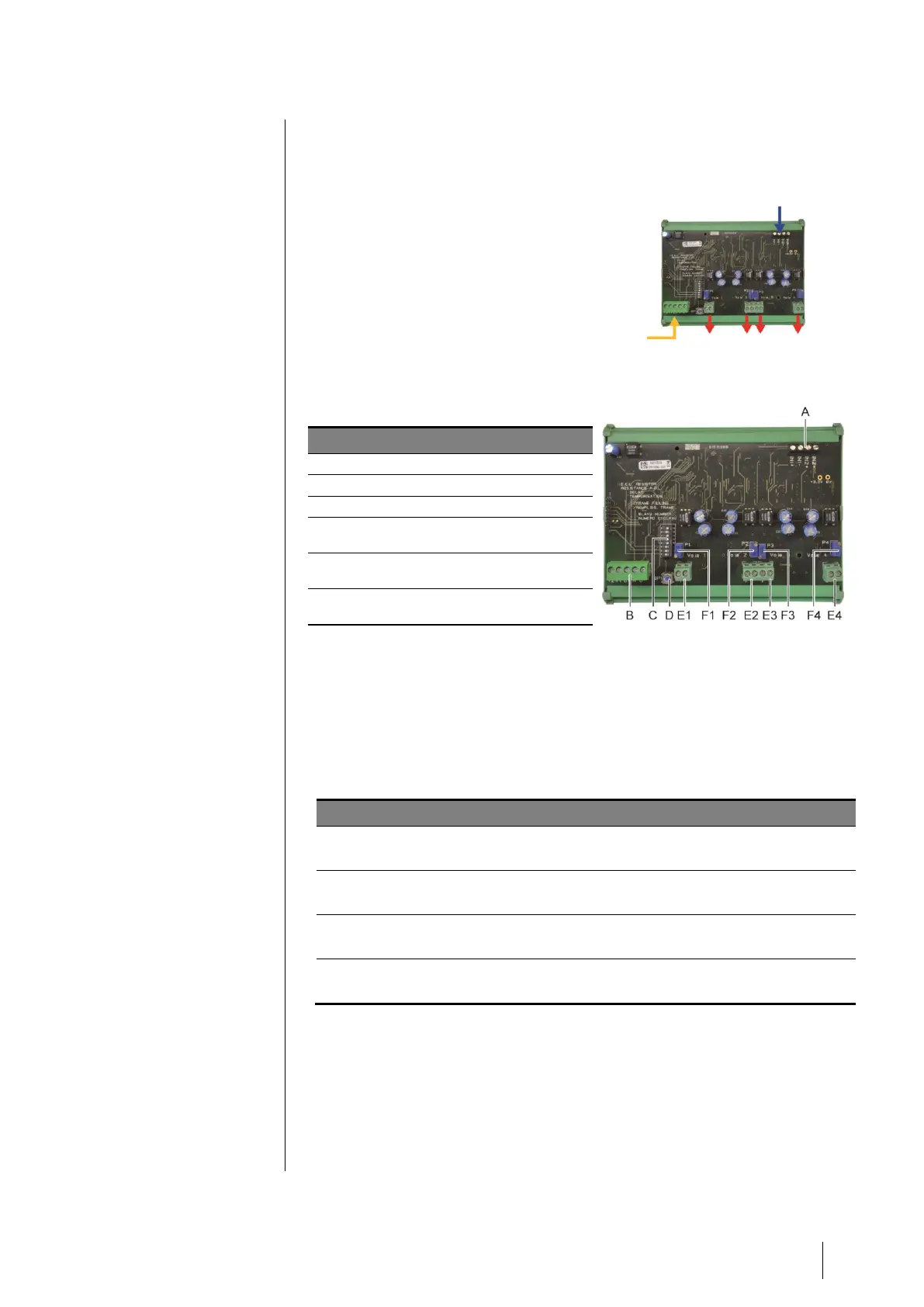
Figure 20: 4 Analog Output Module
Introduction
Power supply and RS485 network
DIP switches for module configuration
Push-button. Pressing this button
forces all outputs to 20mA
(E1 to E4) discrete opto-isolated
4-20mA analog outputs
(F1 to F4) current output settings.
Press D and set to 20mA
Figure 21: 4 Analog Output Module
A – Logic input connectors
Each of these two terminals (Figure 21) may be connected to a voltage-free
contact in accordance with Figure 31
C – Module configuration DIP switches
These switches are set according to the following table:
Slave number
Numéro esclave
See details in the paragraph Module Address on page 18
Frame filling
Remplissage de trame
Factory settings. Do not modify
Factory settings. Do not modify
E.O.L. Resistor
Résistance F.D.L.
See details in paragraph End of line Resistor, on page 19
Table 9: Analog Output Module Configuration DIP switches
Connection
Refer to Chapter 6, on page 27
Configuration
Configured via the COM 32 application