30 MX43
User manual
16-Logic Input Module
Function
This digital module allows the
monitoring of 1 to 16 logic inputs by the
MX43.
In the 8-line version, the central unit
can manage a maximum of 32 logic
inputs distributed, for example, either
on 32 logic input modules with one
input declared per module, or on 2
modules with 16 logic inputs each.
In the 4-line version, the central unit
can manage a maximum of 16 logic
inputs.
110
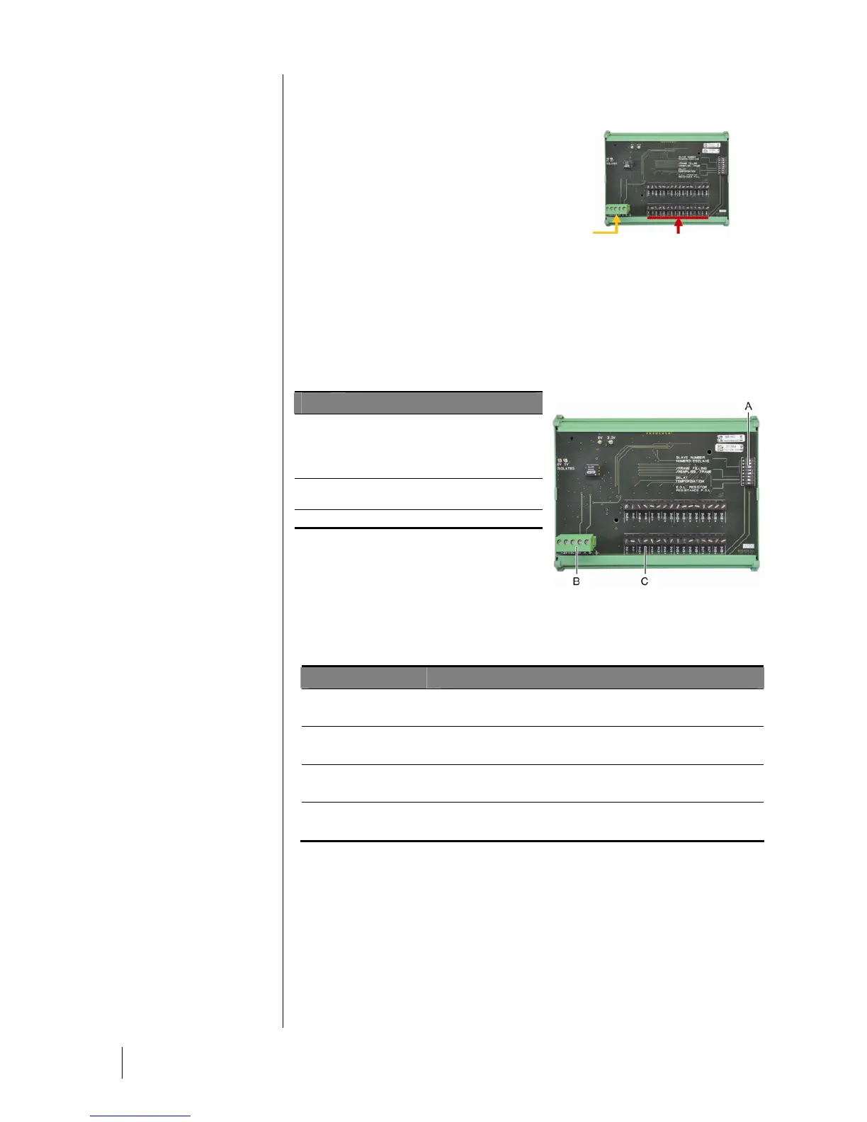
Figure 19: Module with 16 logic inputs.
Introduction
Ref.
Description
A.
Module configuration switches (digital
address, delay, and end of line
resistor).
B.
Power supply and digital network
connector.
C.
Logic inputs 1 to 16.
104
Figure 20: Module of 16 logic inputs.
A – Module configuration switches
These switches are set according to the following table:
Term
Symbol
Slave number
Numéro esclave
See details in paragraph Module Address on page 26.
Frame filling
Remplissage de trame
Factory settings. Do not modify.
Delay
Temporisation
Factory settings. Do not modify.
E.O.L Resistor
Résistance F.D.L.
See details in paragraph End of line Resistor on page 27.
Table 7: Configuration switches of the Logic input module.
C –Logic input connectors
Each of these 16 inputs can be connected to a voltage-free contact as per Figure
35. Input status is transmitted by the digital line to the MX43. There is no alarm
when the contact is closed.
Connection
Refer to chapter 6 on page 35.
16 logic inputs
Digital line
4 wires