28 MX43
User manual
Relay modules
Function
This digital module, available in two
versions, allows for the management
of:
■ 1 to 4 relay outputs;
■ Or 1 to 8 relays.
In addition, it has 2 logic inputs.
108
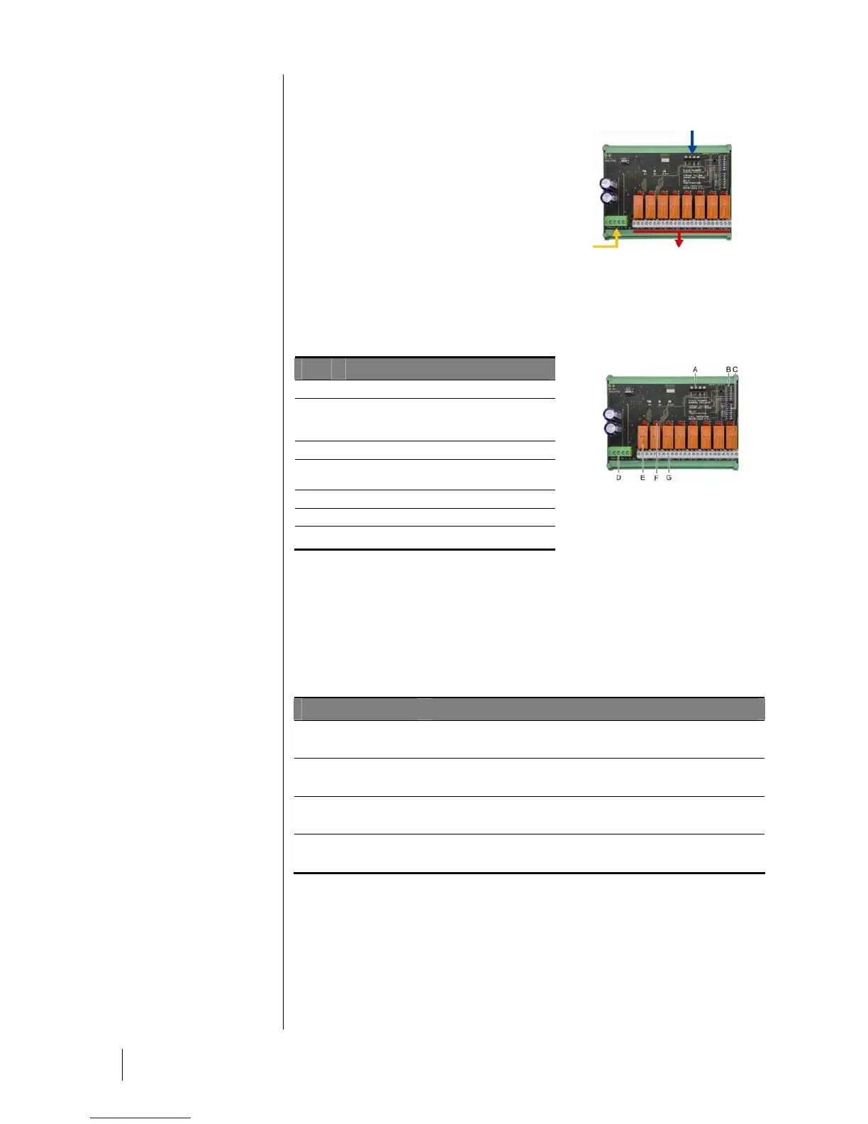
Figure 17: 8-relay module.
Introduction
Ref..
Description
A.
Connector for 2 logic inputs.
B.
Configuration switches of the module
(digital address, delay, and end of line
resistor).
C.
Switches for relay configuration.
D.
Power supply and digital network
connector.
E.
Programmable relay (4 or 8).
F.
Relay status indicator.
G.
Connection terminal.
100
Figure 18: 8-relay module.
A – Logic input connectors
Each of these two terminals (Figure18 A) may be connected to a voltage-free
contact as per Figure 34. There is no alarm when the contact is open.
B – Module configuration switches
These switches are set according to the following table.
Term
Symbol
Slave number
Numéro esclave
See details in the paragraph Module Address on page 26.
Frame filling
Remplissage de trame
Factory settings. Do not modify.
Delay
Temporisation
Factory settings. Do not modify.
E.O.L Resistor
Résistance F.D.L.
See details in paragraph End of line Resistor, on page 27.
Table 6: Relay module configuration switches.
C: Relay configuration switches
The output status of each relay also depends on the configuration of
Positive/negative safety set by this switch block (Figure 18, C). Set the switch to
ON (positive safety) or OFF (negative safety) according to the safety type desired;
each switch acts on the relay having the same number (switch 1 acts on relay 1).
Digital line
4 wires
2 logic inputs
4 or 8 output relays
(CRT 250 VAC – 2A)