32 MX43
User manual
Connection
Refer to chapter 6 on page 35.
Configuration
Configured via the COM 43 application.
Note related to manual calibration of the detectors connected to an 8-
analog input module.
4 -20mA Detectors
1. Zero calibration
Inject standard gas to obtain 4 mA. Place the multimeter between points D and G
(Figure 22). If the value measured is different from 0.4 V, adjust C.
2. Sensitivity calibration
After injecting the gas, place the multimeter between points D and G (Figure 22). If
the value measured is different from 2.0 V, adjust B.
Should the adjustment value be different, calculate:
V= I (mA) x 0.10 (V/mA)
Example: If the current is 12 mA, “V” must be equal to 1.2 V.
Bridge Detectors
1. Zero calibration
Inject standard gas to get 4 mA. Place the multimeter between points E and D
(Figure 22). If the value measured is different from 0.4 V, adjust C.
2. Sensitivity calibration
After injecting the gas, place the multimeter between D and G. If the value
measured is different from 1.6 V, adjust B.
Should the adjustment value be different, calculate:
V= x (% of range) x 1.6V
Example: For a sensitivity of 60%, “V” must be equal to 0.96 V.
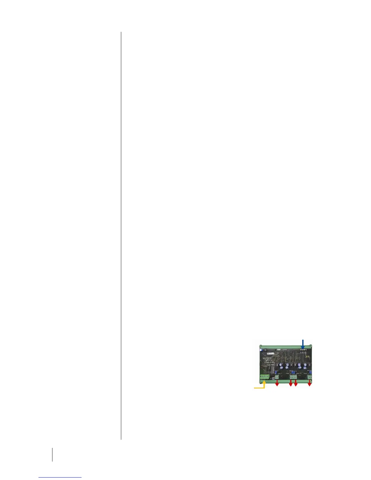
4-Analog Output Module
Function
This digital module delivers 1 to 4
independent analog values (4-20 mA
outputs) opto-isolated from the values
given by the MX43, capable of being
independently activated or deactivated:
■ Activated: The 4-20mA signal varies
depending on the input.
■ Deactivated: The 4-20mA signal is
blocked at 0 mA, whatever the input
signal.
112
Figure 23: Principle 4-analog output
module.
Several analog values may be associated to the same 4-20mA output
4 analog outputs
4-20 mA
2 logic inputs
Digital line
4 wires