6 – Digital Modules 33
authorizing the management of minimums, maximums, or averages from a
group of detectors This module likewise has 2 logic inputs.
Introduction
Ref.
Description
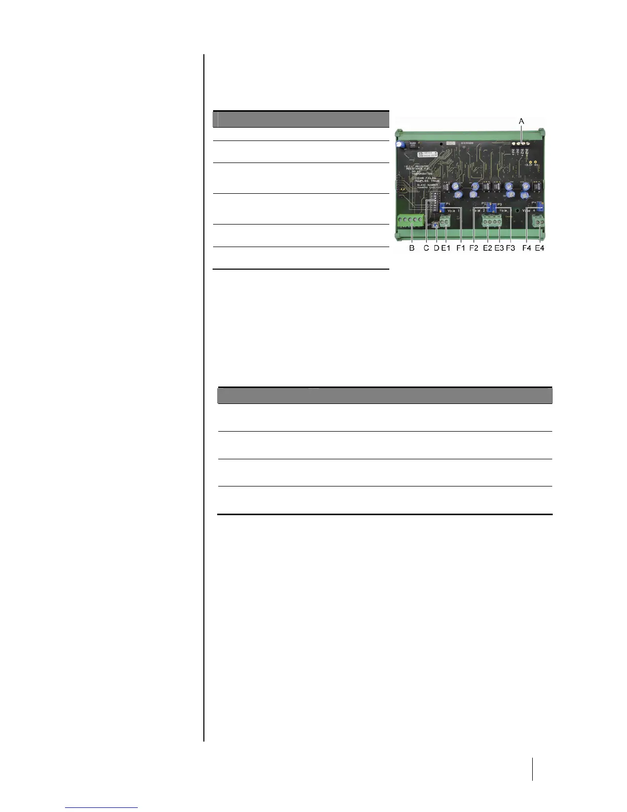
A.
Connector for 2 logic inputs.
B.
Power supply and digital network
connector.
C.
Module configuration switches (digital
address, delay, and end of line
resistor).
D.
Push-button. Pressing this button
generates 20mA current in the output
of each line.
E.
(E1 to E4) opto-isolated independent
4-20mA analog outputs.
F.
(F1 to F4) 20mA calibration in line
output.
114
Figure 24: 4-analog output module.
A –Logic input connectors
Each of these two terminal jacks (Figure 24, A) may be connected to a voltage-
free contact in accordance with Figure 38. Input status is transmitted by the digital
line to the MX43.
C – Module configuration switches
These switches are set according to the following table:
Term
Symbol
Slave number
Numéro esclave
See details in paragraph Module Address on page 26.
Frame filling
Remplissage de trame
Factory settings. Do not modify.
Delay
Temporisation
Factory settings. Do not modify.
E.O.L. Resistor
Résistance F.D.L.
See details in paragraph End of line Resistor on page 27.
Table 9: Analog output module configuration switches.
Connection
Refer to chapter 6 on page 35.
Configuration
Configured via the COM 43 application.