38 MX43
User manual
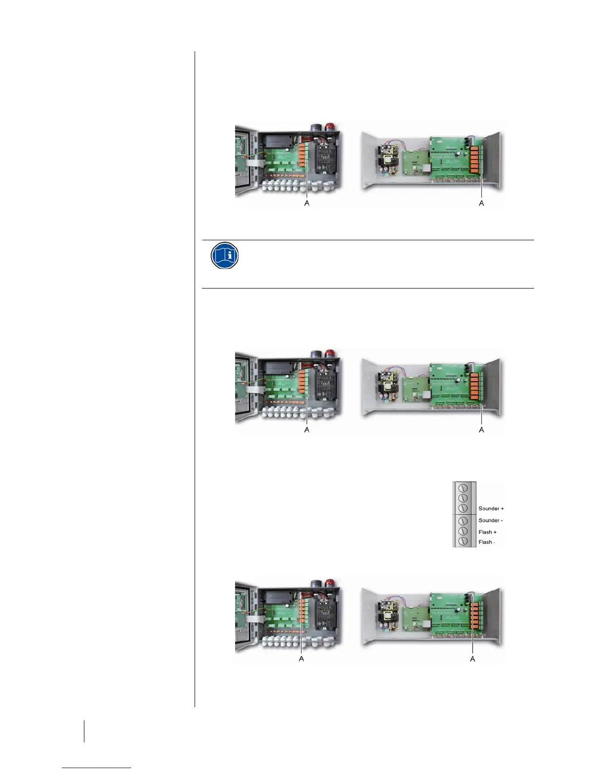
The RCT dry contacts (nominal resistive load of 2 A at 250 VAC, and 2 A 30 V DC) of the 6
internal relays R1, R2, R3, R4, R5 and Default are deployed on the backplane board of
MX43 on the R1, R2, R3, R4, R5 and Default connectors (Figure 30: Internal alarm relay
connectors (A).
).
066
Figure 30: Internal alarm relay connectors (A).
Connect the external equipment to the control on terminal jacks R1 to R5.
The relays are represented as disconnected. The position of the
contacts (no alarm) once the MX43 is powered will depend on the
purpose of the relay configuration (positive or negative safety).
The relays are programmed via the COM 43 application.
Remote Release Connector
If necessary, connect the RELEASE (dry contact NO) terminal to a remote
release system.
068
Figure 31: Remote release connection (A).
Flash and Siren Control Connector
This connector, powered at 24VDC by the MX43,
allows power supply for a rotating light and a siren
optionally available for the MX43 in wall-mounted
version. In the rack version, these connectors may
be taken over to power a sound alarm (24VDC,
19mA max.) and a visual alarm (24 VDC, 40 mA
max.). Ensure to match the polarities.
082
Figure 32: Flash and siren
connector (A).
070
Figure 33: Location of the flash and siren connector (A).