2
Fig.
5
Fig. 6
Fig. 7
Fig. B
•
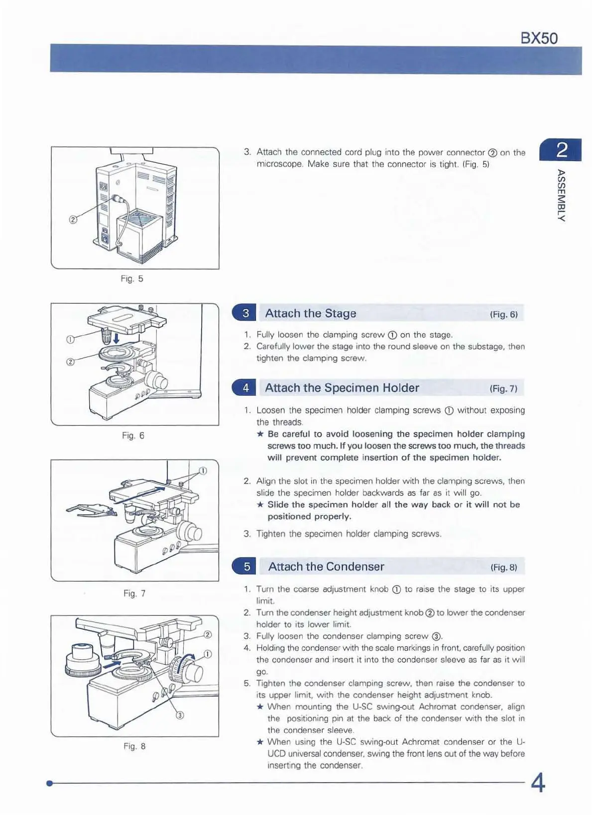
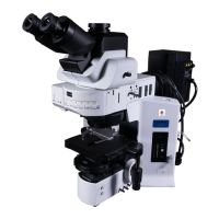
3.
Attach the connected cord plug Into the
power
connector
<i)
on t
he
microscope. Make sure that t
he
connector
IS
tight.
(Fig.
5)
..
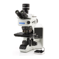
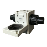
Attach
the
Stage
(F
ig.
6)
1.
Fully loosen the clamping
screw
<D
on the stage.
2.
Carefully lower the stage into the round sleeve on the substage, then
tighten the
damping
screw
.
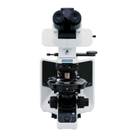
• Attach the Specimen Holder
(Fig.
7)
1. Loosen the specimen holder clamping screws
<D
wi
thout exposing
the
threads.
* Be careful
to
avoid loosening the specimen holder clamping
screws
too
much.
If
you
lo
osen the screws
too
much
, the threads
will
prevent complete insertion
of
the specimen holder.
2.
Align the slot
In
the specimen holder with the clamping screws, then
slide the specimen holder backwards
as
far
as
it will go.
* Slide
the
specimen holder all
the
way
back or
it
will
no
t be
positioned
properly
.
3. T
IQhten the specimen holder clamping screws.
..
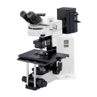
Attach the Condenser
(Fig.
8)
1.
Turn the coarse adjustment knob
CD
to raise the stage to its upper
limit.
2. Turn the condenser height adjustment knob
<i>
to lower the condenser
holder to
Its lower limit.
3.
Fully loosen the condenser clamping screw @.
4. Ho
ld
ing the condenser
With
t
he
sca
le markings
in
front.
ca
refully position
the condenser and insert it into the condenser sleeve
as
far
as
it will
go.
5.
Tighten the condenser clamping screw, then raise the condenser to
its upper
limit,
with
the condenser height adjustment knob.
* When mountmg the
U-SC
SWlng-out Achroma! condenser, align
the
poSitIOning pin at the back of the condenser with the slot
in
the condenser sleeve.
* When uSing the
U-SC
swing-out Achromat condenser or the
U·
UCD
universal condenser, swing the front lens out of the
way
before
Inserting the condenser.
4