32
Installation (continued) Step Five
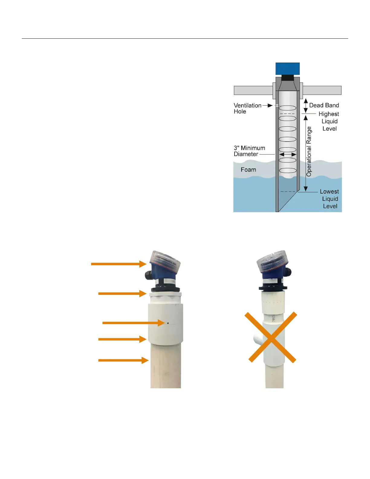
5. Stand Pipe: A standpipe maybe used to dampen turbulence or when foam is present in the
application.
a) Pipe can be constructed from any material.
b) Select a minimum 3” ID pipe or greater for the stand pipe.
i) Select a minimum 4” ID pipe for the US12 series.
c) Use a coupling and reducer bushing to attach the LVU700
series to the pipe.
i) Use a reducer bushing such as LVU800-3N80 (3”
Thread x 2” Thread) fitting or the LVU800-3S80 (3” Slip
x 2” Thread) fitting.
d) The pipe length should run the measurement span. The
bottom of the pipe should remain submerged at all times to
prevent foam from entering the pipe.
e) Cut a 45° notch at the bottom of the pipe. Drill a
1/4”pressure equalization hole in the dead band.
f) The pumps should not drive liquid past the open end of the
stand pipe which causes the liquid in the pipe to oscillate.
Note: Never allow the bottom of the stand pipe to become
exposed to air. This will break the liquid seal which will
prevent echoes from returning back to the sensor.
LVU700
series
3” x 2”
Reducer Bushing
(TxT)
Vent Hole (1/4”)
3” Coupling
(S x T)
3” PVC Pipe
LVU700 series attached to a
LVU800-3S40 (3” x 2” reducer
bushing) to a Slip x Thread 3”
Coupling.
Avoid the use of a tee within the
stand pipe. A tee can create false
signals impeding the sensor’s
performance.
 Loading...