33
Wiring Step Six
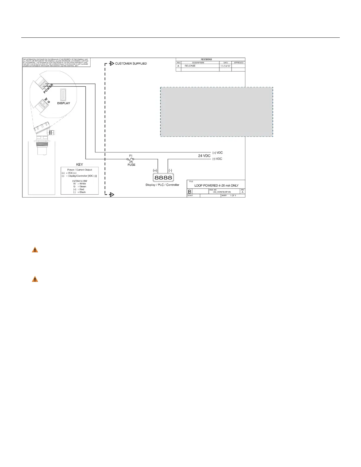
WIRING DIAGRAM - SAMPLE
WIRING LVU700 SERIES
Once LVU700 series has been configured; follow the Wiring Diagram provided by the LVCN414-SW software.
A typical wiring diagram is shown above. OMEGA ENGINEERING recommends using a qualified licensed
electrician to wire LVU700 series with your application’s components.
Configure your LVU700 series with LVCN414-SW software and use the wiring diagram button to view
the appropriate diagram. Each configuration will have its own unique diagram. The diagram shown
above is only a sample and should not be used as a wiring diagram.
The analog output of the LVU700 series is a loop powered 4-20 mA control circuit. The typical way to
use this feature is to connect a positive supply to the (+) input and to sense the current flow out of the (-
) output.
SampleWiringDiagram
Diagram will change based upon
the sensor’s configuration, use
LVCN414‐SW software to view
appropriatewiringdiagram.
 Loading...