3
Introduction / Table of Contents Step One
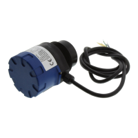
An ultrasonic sound wave is pulsed from the base of the transducer. The sound wave reflects against the
process medium below it. The sound wave energy is returned to the transducer. The microprocessor based
electronics measures the time of flight between the sound pulse generation and its receipt. This translates into
the distance or range between the transducer and process media below.
NEW FEATURES
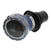
Reflective Ultrasonic Technology
Simple configuration with push button or LVCN414-SW software configuration
Increased temperature range
Increased output filtering
TABLE OF CONTENTS
Introduction: ...................................................................................................................................................... 3
Specifications: ........................................................................................................................................... 5
Dimensions: .............................................................................................................................................. 6
Reflective Technology: .............................................................................................................................. 7
About this manual: .................................................................................................................................... 8
Getting Started: ..................................................................................................................................................... 9
Setup Overview: ........................................................................................................................................ 9
Components: ............................................................................................................................................ 1-
LVCN414-SW software vs. Display Configuration: ................................................................................. 11
Understanding Sensor Height (Height): .................................................................................................. 12
Understanding Fill-Height (Fill-H): ...................................................................................................... 13-14
Sensor Output to Local Display: ............................................................................................................. 15
Configuration (with LVCN414-SW software): ..................................................................................................... 16
Step 1 – Install LVCN414-SW software: ................................................................................................. 17
LVCN414-SW software System Requirements: .......................................................................... 17
USB Fob Interface: ...................................................................................................................... 18
Step 2 – Measure the Tank: .................................................................................................................... 19
Step 3 – Sensor Configuration: ............................................................................................................... 20
Step 4 – Dimensional Entry: ................................................................................................................... 21
Step 5 – Tank Level Confirmation: .......................................................................................................... 22
Step 6 – Write to Unit: ............................................................................................................................. 22
Configuration
(
with Display): ................................................................................................................................ 23
Step1 – Measure Tank: ........................................................................................................................... 24
Step 2 – Setting the Units of Measurement: ........................................................................................... 25
Step 3 – Setting the Height: .................................................................................................................... 26
Step 4 – Setting the Fill-H: ...................................................................................................................... 27
Step 5 – Setting the Fail-Safe Current Output: ....................................................................................... 28
Installation: .......................................................................................................................................................... 29
Mounting Guide: ...................................................................................................................................... 29
Fitting Selection: ................................................................................................................................ 30-32
 Loading...