710.1760.00.04-05 22/05/2014
34
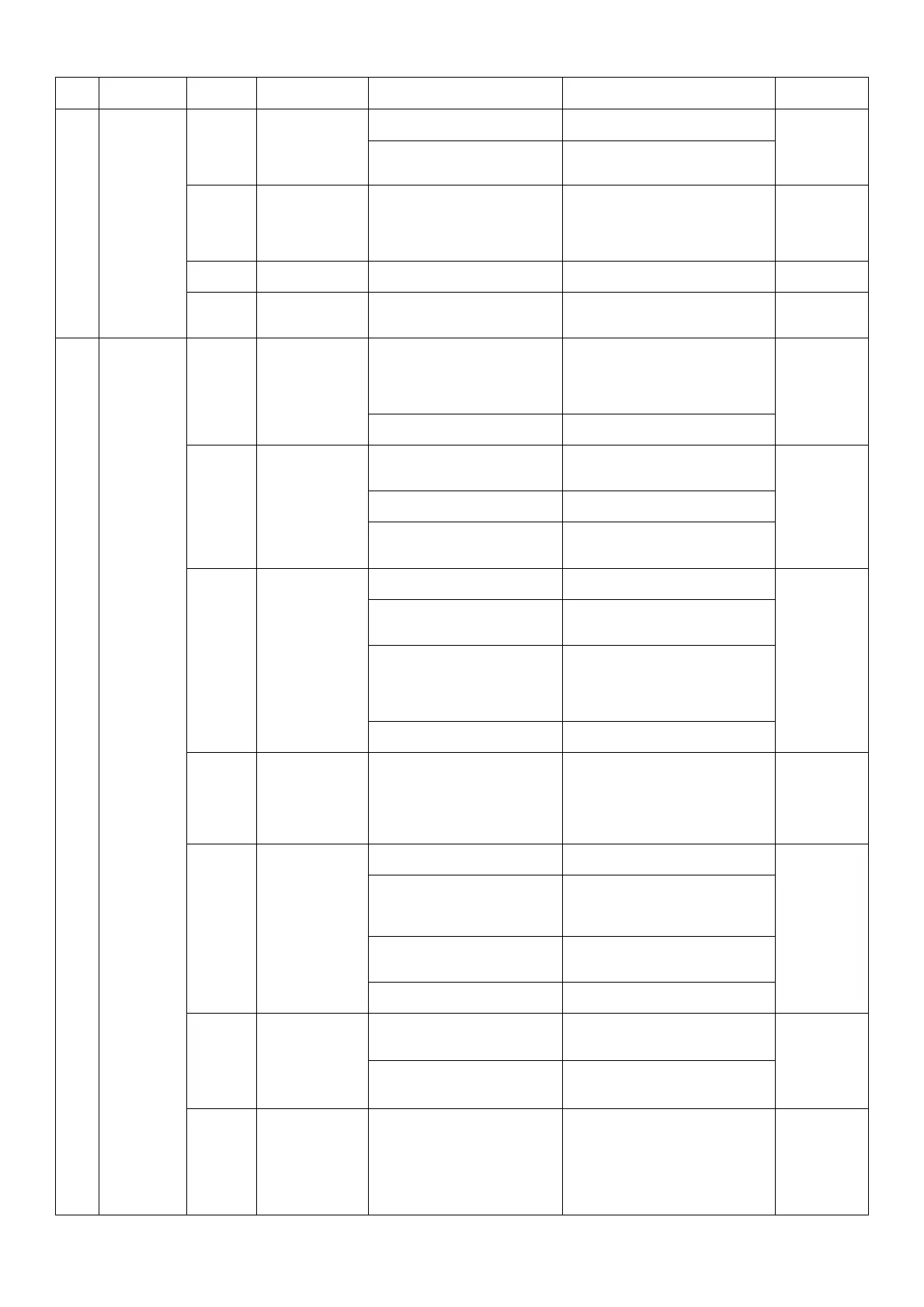
No. Device
status
Alarm
code
Alarm de-
scription
Possible cause Recommended remedy Restore (*)
1
Fan, Com-
pressor and
pump are
not working
A09
Pump thermal
switches alarm
Thermal protections of a new
unit are in OFF position
Switch MTP in ON
M after reset
MTP
Pump is having problem
Check pump and possible ob-
struction on liquid circuit
ACF1
ACF2
ACF3
ACF4
ACF5
Configuration
alarm
Parameters set up in a
wrong way
Check parameter setup A
AFR
Frequency
alarm
The frequency of power sup-
ply is out of range
Check correct power supply A
EE Eeprom run
Internal problem of the con-
troller
Reset alarm and in case of
persistent problem change
controller
M
2
Fan and
compressor
are not
working,
pump is
working
A01
Refrigerant
high pressure
alarm
Ambient temperature too
high
Decrease ambient temperature,
increasing ventilation of the
room, removing heat sources or
repairing the unit from the di-
rect rays of sun
M after reset
high pres-
sure switch
using button
on it if pre-
sent
Dirty condenser
Clean the condenser as de-
scribed in maintenance
A01
Refrigerant
high pressure
alarm
Fan is not working fine or
the sense of rotation is not
correct
Check fuse of the fan, and right
rotation
M after reset
high pres-
sure switch
using button
on it if pre-
sent
Required cooling capacity is
higher than nominal
Decrease the required cooling
capacity
Air filter dirty (only for units
with this kind of option)
Dismount the filter from the
unit and clean it with air or with
water
A02
Refrigerant low
pressure alarm
Unit low on refrigerant
Check liquid sight glass and in
case contact service
A
becomes
M after 10
events in 1
hour
Liquid flow too low
Check right rotation of pump
and possible obstruction on liq-
uid circuit
Percentage of antifreeze too
low or not present, even for
range of temperature higher
than 5°C
Add antifreeze, or try to in-
crease temperature or flow of
liquid the combination of these
three element can cause ice
problem
Dirty evaporator
Clean evaporator and in case
contact service
A05
High liquid
temperature
alarm (if P3 or
P4 high temp.
alarm is pre-
sent)
Required cooling capacity is
higher than nominal
Decrease the required cooling
capacity
M
A07
Antifreeze
alarm
Percentage of antifreeze too
low
Add antifreeze to the liquid
M
Set point is too low for actu-
al system
If possible increase set point, or
check combination of flow,
temperature and antifreeze
percentage
Liquid flow too low
Check right rotation of pump
and possible obstruction on liq-
uid circuit
Dirty evaporator
Clean evaporator and in case
contact service
A09
Compressor
thermal switch
alarm
Thermal protection of a new
unit are in OFF position
Switch MTC in ON
M after re-
set MTC
Compressor is having prob-
lem
Reset thermal switch and in
case contact of a persistent
problem contact service
A16
High liquid
temperature
alarm in inlet
line (if P3 or P4
high temp.
alarm is pre-
sent)
Required cooling capacity is
higher than nominal
Decrease the required cooling
capacity
A
becomes
M after 3
events in 1
hour