B7AP
B7AP
112
Precautions
General Precautions
Be careful when touching the
B7AP-S1 Power Coupler during op
-
eration because the surface temperature of the B7AP-S1 Power
Coupler
will rise approximately 20
°
C after the
B7AP-S1 Power Cou
-
pler
starts power transmission. The surface
temperature varies with
the load of the sensing device connected to the B7AP-M1 Power
Coupler
and the transmission distance.
Correct Use
Handling
Use
the B7AP-S1 and B7AP-M1 Power Couplers with the available
B7A
Link T
erminals. Refer to
page
21, B7A Models
.
The M7E-12jj Display Unit, M7E-20jj Display Unit, and B7A
Link
T
erminals with an I/O delay time of 3 ms cannot be used with the
B7AP-S1
or B7AP-M1 Power Coupler
.
Use
the LOAD-OFF model for the B7A
Output Unit to be connected
to
the B7AP-S1. When using a model that allows selection of error
processing, set to the LOAD-OFF mode. This turns OFF signals
right
before an occurrence of a transmission error and prevents un
-
expected signal transmission when the transmission error is
cleared.
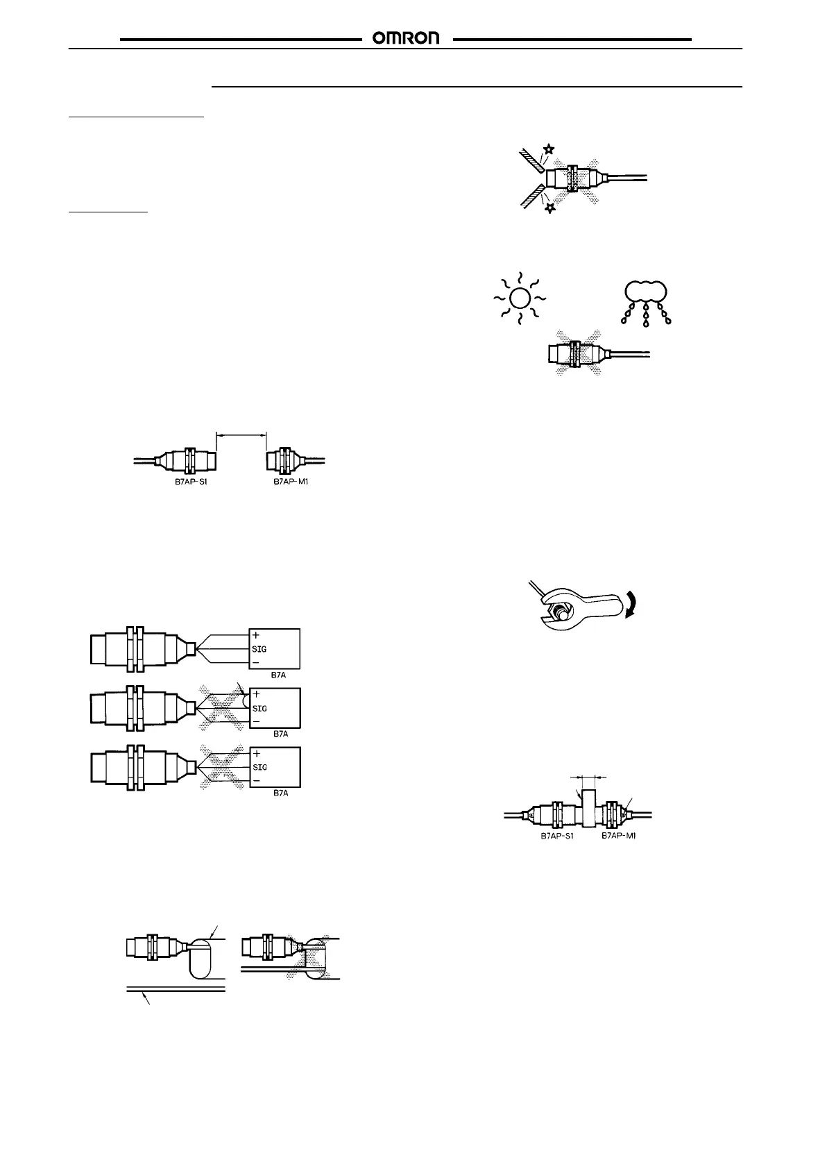
Separate
the Power Couplers 8
±
1.5 mm min. away from each other
.
The
distance between the
Power Couplers on standby must be 30
mm
or more.
30
mm min.
Do not supply power to the B7AP-S1 or B7AP-M1 Power Coupler
while connecting the Power Couplers to the B7A Link Terminals.
Connect the Power Couplers to the B7A Link Terminals correctly,
otherwise
the internal circuits of the Power Couplers may be dam
-
aged.
The
SIG terminal must not contact with the power supply terminals,
otherwise
the internal elements may be damaged and normal trans
-
mission
may not be possible.
Brown(+)
Black(SIG)
Blue(–)
Brown(+)
Black(SIG)
Blue(–)
Brown(+)
Black(SIG)
Blue(–)
Correct
Incorrect
Incorrect
Contact
Wire the cables of the B7AP-S1 and B7AP-M1 Power Couplers
through
independent metal conduits to prevent the Power Couplers
from being influenced by noise if there are power or high-tension
lines
nearby
. T
est the Power Couplers and make sure that the Pow
-
er Couplers operate normally before they are put in actual opera-
tion.
Metal conduit
Power or high-tension line
Correct Incorrect
Do
not subject the head of the
B7AP-S1 or B7AP-M1 Power Cou
-
pler to excessive shock with hard objects.
Do
not use the B7AP-S1 or B7AP-M1 Power Coupler outdoors un
-
less
it is properly protected.
The
B7AP-S1 and B7AP-M1 Power Couplers are products
meeting
the requirements of IP67. The B7AP-S1 or B7AP-M1 Power Cou-
pler
cannot be, however
, used in water or oil.
Keep
the heads of the B7AP-S1 and B7AP-M1 Power Couplers
free
from
dust, otherwise improper signal
or power transmission may re
-
sult
between the Power Couplers.
Mounting
Use nuts and serrated toothed washers and tighten the nuts to
mount
the B7AP-S1 and B7AP-M1 Power Couplers. The tightening
torque
applied to each
of the nuts must be 39 N
S
m maximum. The
mounting
position will change and improper signal or power trans
-
mission
may result between the Power Couplers if the
nuts are not
tightened
properly
.
39 NS
m max.
Transmission Distance for Stable Signal and
Power Transmission
The
B7AP-S1 Power Coupler has a gauge that is used to adjust the
transmission
distance between the B7AP-S1
and B7AP-M1 Power
Couplers. Use the gauge to adjust the transmission distance to
8 mm,
make sure that the green operation indicator of the B7AP-M1
Power Coupler is lit, and the B7A Output Unit has no error output
before
operating the Power Couplers.
Gauge
Operation
indicator
8
mm
Monitoring Transmission Status
Judge
from the power supply/error indicator
and error output of the
B7A
Output Unit whether the B7AP-S1 and B7AP-M1 Power Cou
-
plers
are facing each other properly
.
The
error output of the B7A Output Unit will be ON when the B7AP-
S1
and
B7AP-M1 Power Couplers are not facing each other proper
-
ly.