3 Check and start operation
3-1 The name and function for the operation and display
3 Check and start operation
3-1 The name and function for the operation and display
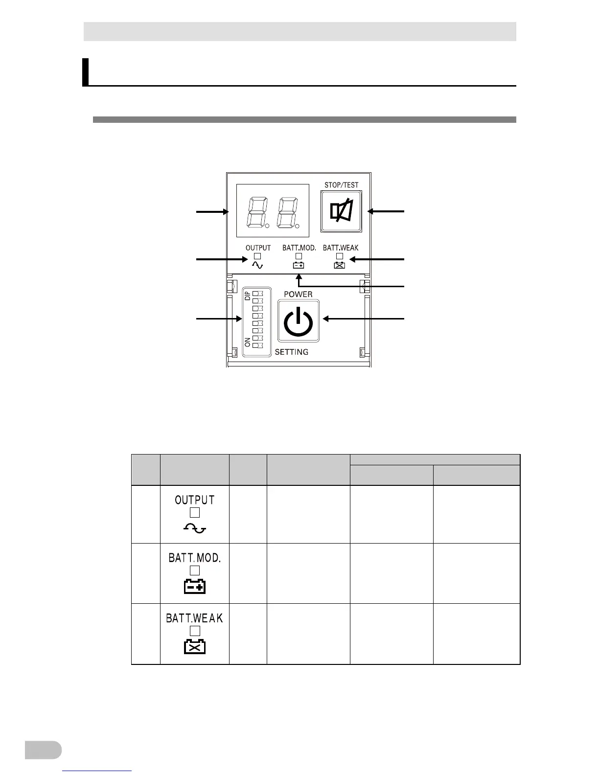
3-1-1 Name of each part
A
B
E
G
D
C
F
A: Status indicator
B: “Power supply output” LED
C: “Battery mode” LED
D: “Battery replacement” LED
E: “Setting switch”
F: “Power” switch
G: “Buzzer Pause/Test” switch
<Enlarged view of the operation panel>
3-1-2 The meaning of each LED
Sign of
the
LED Color Name Status
Lit. Not lit.
B
Green “Power supply output”
LED
The power supply
output is ON.
output i s O F F.
C
Orange “Battery mode” LED Backup is operating.
This status is called
“Battery Mode”.
operating.
D
Red “Battery replacement”
LED
end of battery life.
Battery replacement is
not necessary.
BA75T/BA100T/BA100R
34