52
Data Area Allocation for Built-in I/O Section 4-1
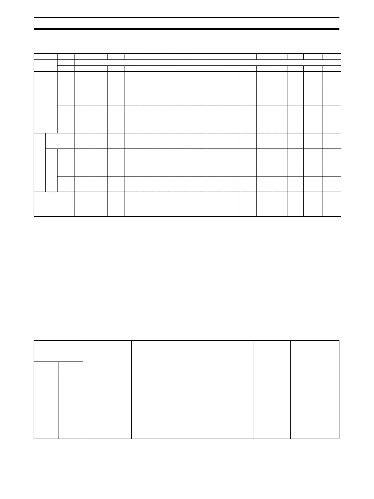
4-1 Data Area Allocation for Built-in I/O
Note PWM(891) output 1 cannot be used on the CJ1M-CPU21.
4-2 PLC Setup Settings
4-2-1 Built-in Inputs
The following tables show the CX-Programmer's settings. These settings are
for CJ1M CPU Units equipped with the built-in I/O functions.
Note CX-Programmer Tabs
CX-Programmer Ver. 3.1 or lower: Built-in I/O Settings
CX-Programmer Ver. 3.2 or higher: Built-in Input
High-speed Counter 0 Operation Settings
High-speed Counter 0 Enable/Disable
I/O Code IN0 IN1 IN2 IN3 IN4 IN5 IN6 IN7 IN8 IN9 OUT0 OUT1 OUT2 OUT3 OUT4 OUT5
Address CIO 2960 CIO 2961
Bit0001020304050607 080900010203 04 05
Inputs General-
purpose
inputs
General-
purpose
input 0
General-
purpose
input 1
General-
purpose
input 2
General-
purpose
input 3
General-
purpose
input 4
General-
purpose
input 5
General-
purpose
input 6
General-
purpose
input 7
General-
purpose
input 8
General-
purpose
input 9
--- --- --- --- --- ---
Interrupt
inputs
Interrupt
input 0
Interrupt
input 1
Interrupt
input 2
Interrupt
input 3
--- --- --- --- --- --- --- --- --- --- --- ---
Quick-
response
inputs
Quick-
response
input 0
Quick-
response
input 1
Quick-
response
input 2
Quick-
response
input 3
--- --- --- --- --- --- --- --- --- --- --- ---
High-
speed
counters
--- --- High-
speed
counter
1
(phase-
Z/reset)
High-
speed
counter
0
(phase-
Z/reset)
--- --- High-
speed
counter 1
(phase-
A, incre-
ment, or
count
input)
High-
speed
counter 1
(phase-
B, decre-
ment, or
direction
input)
High-
speed
counter 0
(phase-
A, incre-
ment, or
count
input)
High-
speed
counter 0
(phase-
B, decre-
ment, or
direction
input)
--- --- --- --- --- ---
Out-
puts
General-purpose
outputs
--- --- --- --- --- --- --- --- --- --- Gen-
eral-pur-
pose
output 0
Gen-
eral-pur-
pose
output 1
Gen-
eral-pur-
pose
output 2
Gen-
eral-pur-
pose
output 3
General-
purpose
output 4
General-
purpose
output 5
Pulse
out-
puts
CW/
CCW
outputs
--- --- --- --- --- --- --- --- --- --- Pulse
output 0
(CW)
Pulse
output 0
(CCW)
Pulse
output 1
(CW)
Pulse
output 1
(CCW)
--- ---
Pulse +
direction
outputs
--- --- --- --- --- --- --- --- --- --- Pulse
output 0
(pulse)
Pulse
output 1
(pulse)
Pulse
output 0
(direc-
tion)
Pulse
output 1
(direc-
tion)
--- ---
Variable
duty ratio
outputs
--- --- --- --- --- --- --- --- --- --- --- --- --- --- PWM(891)
output 0
PWM(891)
output 1
(See
note.)
Origin search Origin
search 0
(Origin
Input
Signal)
Origin
search 0
(Origin
Proxim-
ity Input
Signal)
Origin
search 1
(Origin
Input
Signal)
Origin
search 1
(Origin
Proxim-
ity Input
Signal)
Origin
search 0
(Posi-
tioning
Com-
pleted
Signal)
Origin
search 1
(Posi-
tioning
Com-
pleted
Signal)
--- --- --- --- --- --- --- --- Origin
search 0
(Error
Counter
Reset
Output)
Origin
search 1
(Error
Counter
Reset
Output)
Programming
Console setting
address
Settings Default Function Related
Auxiliary
Area flags/
bits
Time when
setting is read
by CPU Unit
Word Bits
50 12 to 15 0 hex: Don’t Use
Counter.
1 hex*:
Use Counter
(60 kHz).
2 hex*:
Use Counter
(100 kHz).
0 hex Specifies whether or not high-speed
counter 0 is being used.
Note When high-speed counter 0 is
enabled (setting 1 or 2), the
input operation settings for
IN8 and IN9 are disabled. The
input operation setting for IN3
is also disabled if the reset
method is set to Phase-Z sig-
nal + software reset.
--- When power is
turned ON