4 Remote I/O Master Communications
4-30
CJ-series DeviceNet Units Operation Manual for NJ-series CPU Unit(W497)
z Master User-set Allocations Setup Table
z Allocation Size Setup Table
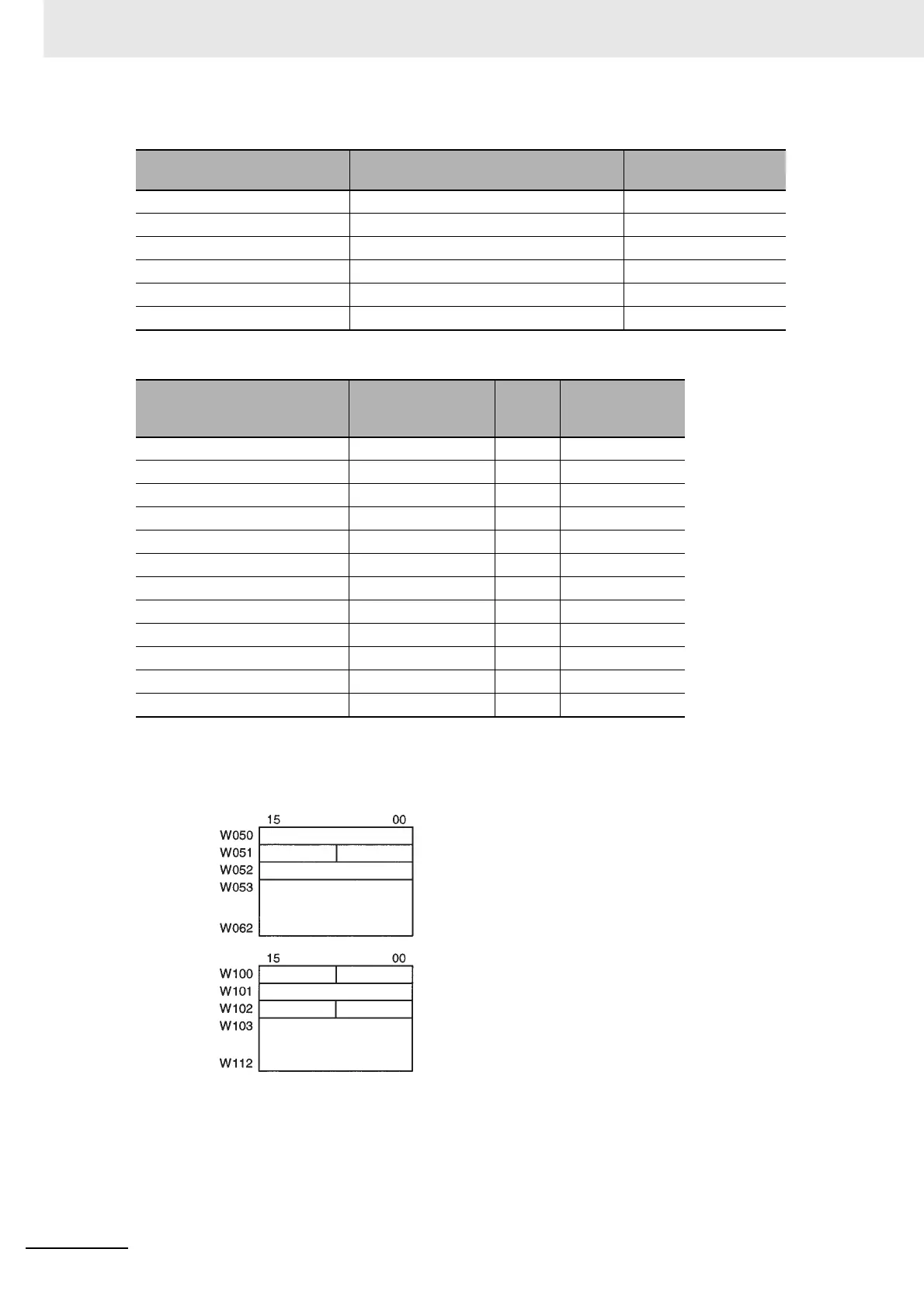
z Resulting Slave Allocations
Slaves are allocated as follows. Before a user program can access the following areas, a user-
defined variable that specifies the AT specification of that allocation area must to be defined.
z Changing the Master User-set Allocations Switch to TRUE
Change *_Sw1MstrAlocCmd (Master User-set Allocations Switch) to TRUE. The Master User-set
Allocations Switch will read the allocation results data for the above slaves and create a scan list
based on data for slaves that are actually online prior to starting remote I/O communications with the
scan list enabled.
Name of device variables for
CJ-series Unit
Name Setting (function)
*_MstrAlocTblCfg[0] OUT block 1 area 4 (WR)
*_MstrAlocTblCfg[1] First word in OUT block 1 50 (50 words)
*_MstrAlocTblCfg[2] IN block 1 area 4 (WR)
*_MstrAlocTblCfg[3] First word in IN block 1 100 (100 words)
*_MstrAlocTblCfg[4] Allocation size setup table area 3 (DM)
*_MstrAlocTblCfg[5] First word in Allocation Size Setup Table 1 100 (100 words)
Address
User-defined vari-
able name (USINT
type)
Setting
Number of slave
bytes
Bits 00 to 07 for D00100 Slave0_InSizeTab 0 0
Bits 08 to 15 for D00100 Slave0_OutSizeTab 2 2
Bits 00 to 07 for D00101 Slave1_InSizeTab 1 1
Bits 08 to 15 for D00102 Slave1_OutSizeTab 1 1
Bits 00 to 07 for D00103 Slave2_InSizeTab 2 2
Bits 08 to 15 for D00103 Slave2_OutSizeTab 2 2
Bits 00 to 07 for D00104 Slave3_InSizeTab 1 1
Bits 08 to 15 for D00104 Slave3_OutSizeTab 0 0
Bits 00 to 07 for D00105 Slave4_InSizeTab 0 0
Bits 08 to 15 for D00105 Slave4_OutSizeTab 0 0
Bits 00 to 07 for D00106 Slave5_InSizeTab 20 20
Bits 08 to 15 for D00106 Slave5_OutSizeTab 20 20
OUT area 1
IN area 1
Address 0
Not used Address 1
Address 2
Address 5
Not used
Address 2
Not used
Address 1
Address 5
Address 0 allocated two bytes (1 word).
Address 1 allocated 1 byte, leftmost byte is not used.
Address 2 allocated two bytes (1 word).
Address 5 allocated 20 bytes (10 words).
Address 1 allocated 1 byte, leftmost byte is not used.
Address 2 allocated two bytes (1 word).
Address 3 allocated 1 byte, leftmost byte is not used.
Address 5 allocated 20 bytes (10 words).
Address 3