122
5-2 The CPM1A Cycle
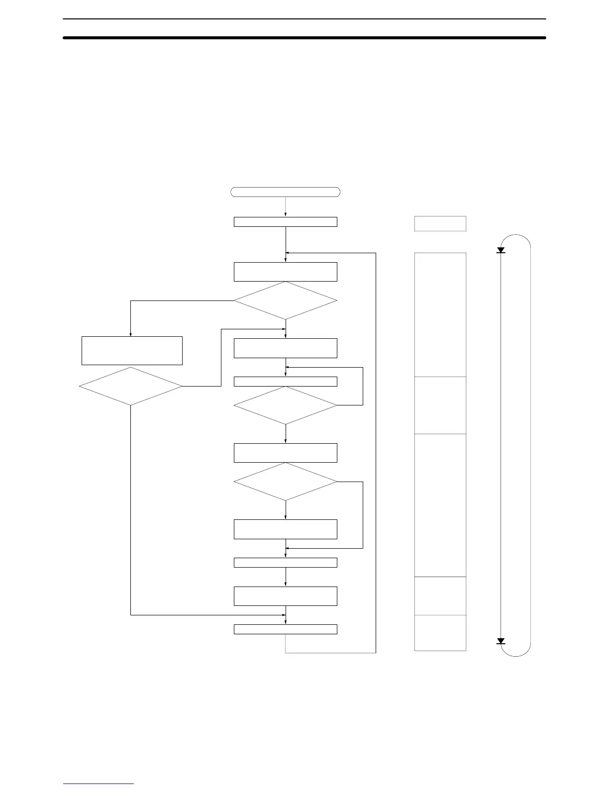
The overall flow of CPM1A operation is as shown in the following flowchart. The
CPM1A is initialized internally when the power is turned on. If no errors are
detected, the overseeing processes, program execution, I/O refreshing, and
Peripheral Device servicing are executed consecutively (cyclically). The aver-
age cycle time can be monitor from a Peripheral Device.
Power application
Check hardware and
Program Memory.
Check OK?
Preset cycle time
monitoring time.
Execute user program.
End of program?
Check cycle time set-
ting.
Minimum
cycle time set?
Wait until minimum cycle
time expires.
Compute cycle time.
Refresh input bits and
output terminals.
Service peripheral port.
Set error flags and
activate indicators.
ERROR or ALARM?
No
ERROR
(lit)
ALARM
(flashing)
Initialization
Overseeing
processes
Program
execution
Cycle time
processing
I/O refreshing
Service
peripheral
port.
Cycle
time
No
Yes
No
Yes
Yes
Initialization processes
Note Initialization processes include clearing the IR, SR, and AR areas, presetting
system timers, and checking I/O Units.
The CPM1A Cycle
Section 5-2