5
1-1-2 I/O Terminal and IR Bit Allocation
The following table shows which IR bits are allocated to the I/O terminals on the
CPM1A’s CPU Units and Expansion I/O Unit.
CPU Units
No. of I/O termi-
nals on the CPU
Unit
10 20 30 40
Power supply AC DC AC DC AC DC AC DC
Model
No.
Relay
outputs
CPM1A-
10CDR-A(-V1)
CPM1A-
10CDR-D(-V1)
CPM1A-
20CDR-A(-V1)
CPM1A-
20CDR-D(-V1)
CPM1A-
30CDR-A(-V1)
CPM1A-
30CDR-D(-V1)
CPM1A-
40CDR-A(-V1)
CPM1A-
40CDR-D(-V1)
Sinking
transistor
outputs
CPM1A-
10CDT-A(-V1)
CPM1A-
10CDT-D(-V1)
CPM1A-
20CDT-A(-V1)
CPM1A-
20CDT-D(-V1)
CPM1A-
30CDT-A(-V1)
CPM1A-
30CDT-D(-V1)
CPM1A-
40CDT-A(-V1)
CPM1A-
40CDT-D(-V1)
Sourcing
transistor
outputs
CPM1A-
10CDT1-A(-V1)
CPM1A-
10CDT1-D(-V1)
CPM1A-
20CDT1-A(-V1)
CPM1A-
20CDT1-D(-V1)
CPM1A-
30CDT1-A(-V1)
CPM1A-
30CDT1-D(-V1)
CPM1A-
40CDT1-A(-V1)
CPM1A-
40CDT1-D(-V1)
CPU
Unit
termi-
nals
Inputs 6 points:
00000 to 00005
12 points:
00000 to 00011
18 points:
00000 to 00011
00100 to 00105
24 points:
00000 to 00011
00100 to 00111
Outputs 4 points:
01000 to 01003
8 points:
01000 to 01007
12 points:
01000 to 01007
01100 to 01103
16 points:
01000 to 01007
01100 to 01107
Expansion I/O Units
Unit I/O Relay output
Transistor output
Sinking outputs Sourcing outputs
20 I/O
points
12 inputs
8 outputs
CPM1A-20EDR
CPM1A-20EDR1
CPM1A-20EDT CPM1A-20EDT1
8 inputs 8 inputs CPM1A-8ED
8 outputs 8 outputs CPM1A-8ER CPM1A-8ET CPM1A-8ET1
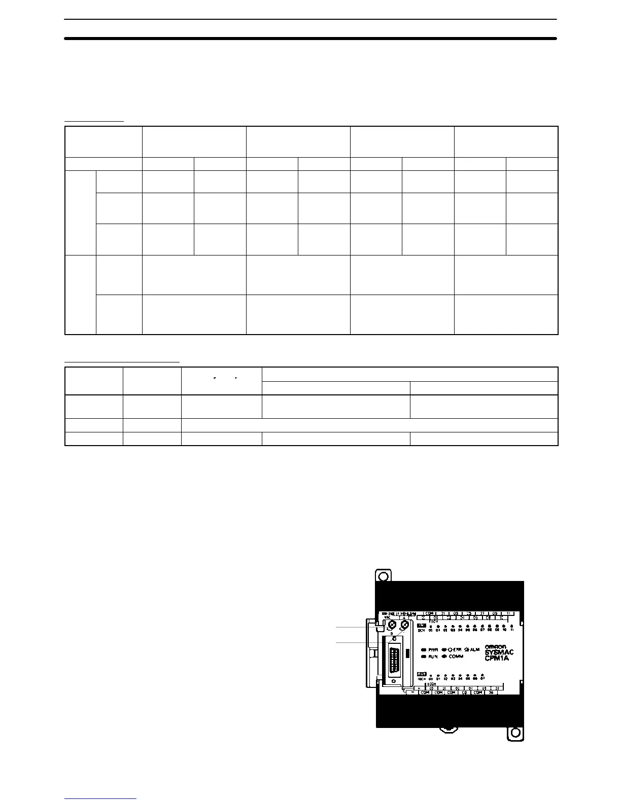
1-1-3 CPM1A Functions
Analog Setting Function CPM1A PCs have 2 variable-resistor adjustment knobs used to control analog
timer and counter settings manually. When one of the adjustments is turned, the
content of the corresponding IR word is set automatically between 0 and 200
(BCD).
Turn the adjustment knob with a Phillips screwdriver.
Analog adjustment 0
Analog adjustment 1
24 VDC 0.2 A
OUT PUT
CPM1A Features and Functions Section 1-1