33
7. PC Status Indicators
These indicators show the operating status of the PC, as shown in the fol-
lowing table.
Indicator Status Meaning
PWR (green)
ON Power is being supplied to the PC.
ON A fatal error has occurred. (PC operation stops.)
(red)
Flashing A non-fatal error has occurred. (PC operation
continues.)
OFF Indicates normal operation.
COMM (orange)
ON Data is being transferred via the Peripheral Port.
OFF Data isn’t being transferred via the Peripheral
Port.
8. Input Indicators
These indicators are lit when the corresponding input terminal is ON.
When a fatal error occurs, the input indicators change as follows:
Fatal error Input indicators
CPU Unit error or I/O bus error Turn OFF.
Memory error, no END instruction
error, or system error
The indicators will change with the
status of the input signal, but input
status will not be updated in memory.
9. Output Indicators
These indicators are lit when the corresponding output terminal is ON.
10. Analog Controls
Setting these controls sets the contents of IR 250 and IR 251 from 0 to 200.
11. Peripheral Port
Connects the PC to a Peripheral Device, RS-232C Adapter, or RS-422
Adapter.
12. Expansion I/O Unit Connector
Connects the PC’s CPU Unit to an Expansion I/O Unit to add another 12
input points and 8 output points. Up to 3 Expansion I/O Units can be con-
nected.
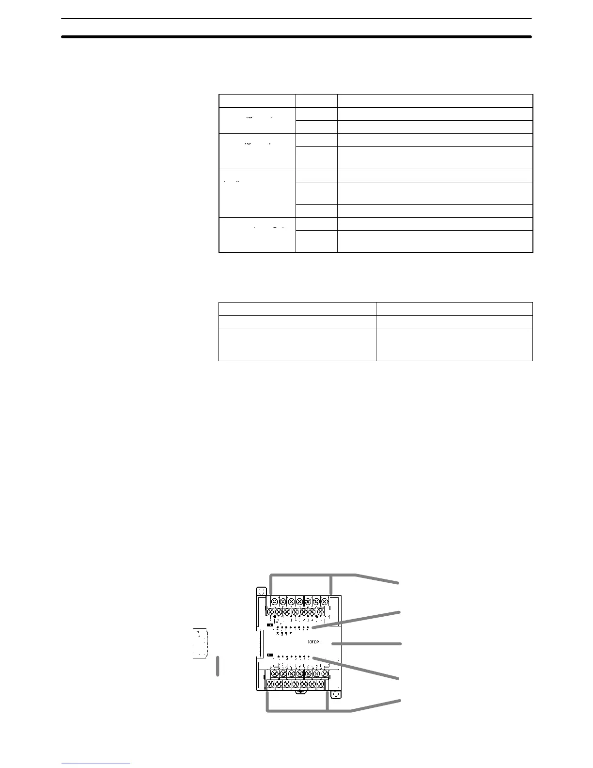
2-2-2 Expansion I/O Unit Components
Expansion I/O Unit with 20 I/O Terminals
1. Input terminals
5. Expansion I/O Unit Connecting Cable
3. Input indicators
6. Expansion connector
4. Output indicators
2. Output terminals
Unit Components
Section 2-2