EasyManuals Logo

Omron CPM1A User Manual

Omron CPM1A
201 pages
To Next Page IconTo Next Page
To Previous Page IconTo Previous Page
Page #70 background imageLoading...
Page #70 background image
47
Installation
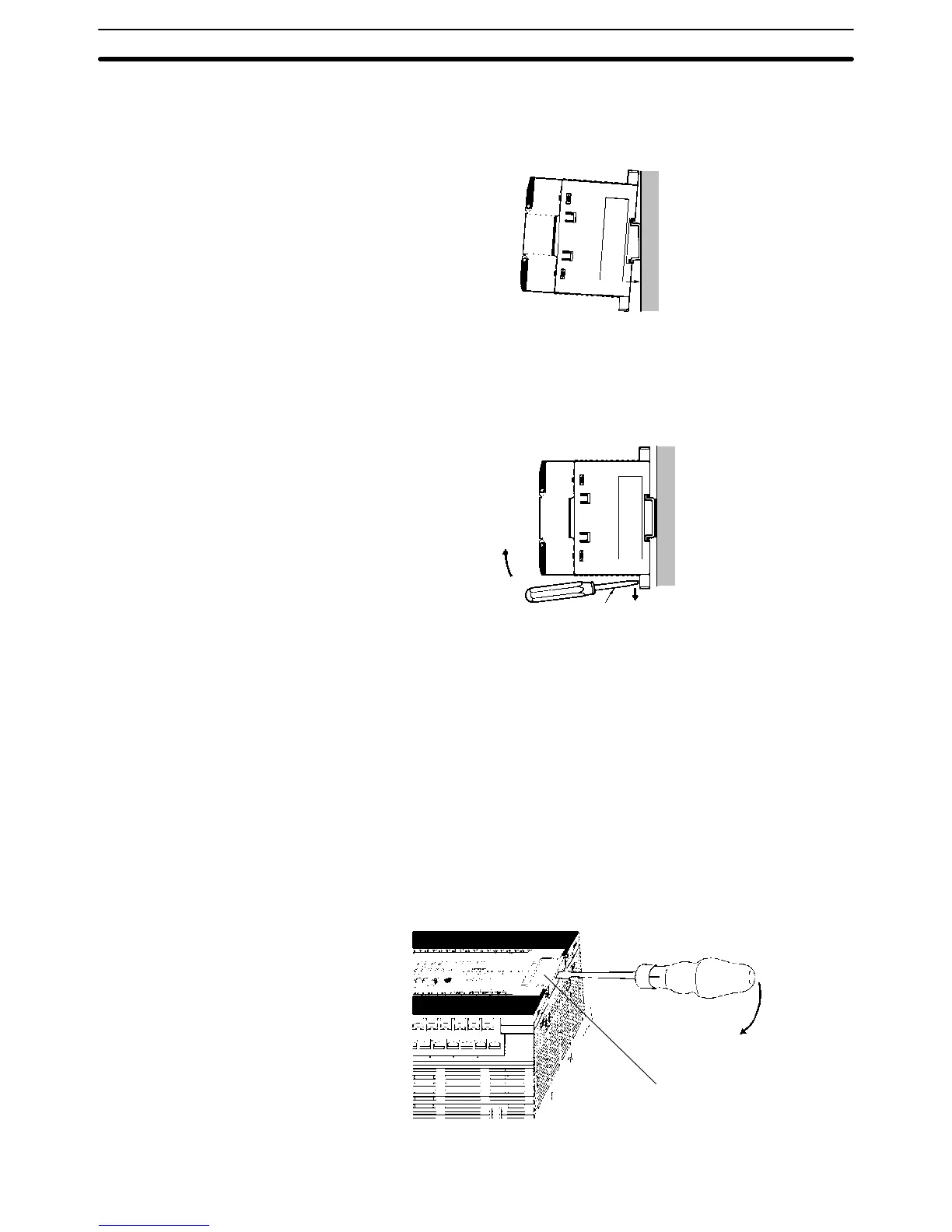
Lower the CPM1A so that the notch on the back of the PC catches the top of the
DIN Track. Push the PC forward until the lock snaps into place.
Removal
Pry the lock down with a standard screwdriver and pivot the PC upward to
remove it.
Screwdriver
3-3-3 Connecting an Expansion I/O Unit
Up to 3 Expansion I/O Units can be connected to the CPM1A-30CDR-(-V1)/
30CDT-(-V1)/30CDT1-(-V1) and CPM1A-40CDR-(-V1)/40CDT-(-V1)/
40CDT1-(-V1) CPU Units. Use the following procedure when connecting an
Expansion I/O Unit.
V1 Units
1, 2, 3... 1. Remove the cover from the CPU Unit’s Expansion I/O Unit Connector. Insert
a flat-blade screwdriver into the slot on the cover and press down lightly on
the handle of the screwdriver to remove it from the case.
Expansion I/O Unit
connector cover
Screwdriver
Installing the CPM1A
Section 3-3

Table of Contents

Other manuals for Omron CPM1A

Questions and Answers:

Question and Answer IconNeed help?

Do you have a question about the Omron CPM1A and is the answer not in the manual?

Omron CPM1A Specifications

General IconGeneral
ModelCPM1A
TypeCompact PLC
Communication PortsRS-232C (optional)
Instruction SetBasic and advanced instructions
Operating Temperature0 to 55°C
Storage Temperature-20 to 75°C
Humidity10% to 90% RH (non-condensing)
Power Supply24 VDC or 100-240 VAC
ExpansionExpansion I/O units available
Timers128
Counters256 counters
I/O Points10, 20, 30, or 40 points (depending on model)

Related product manuals