45
3-3 Installing the CPM1A
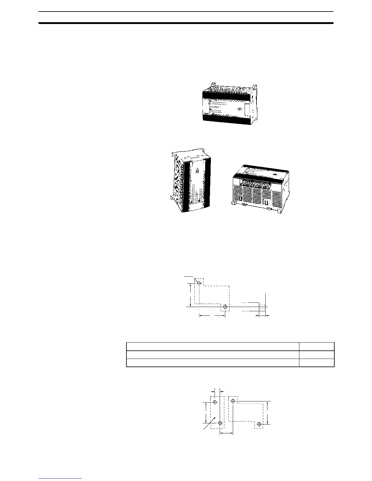
3-3-1 CPM1A Orientation
The CPM1A must be installed in the position shown below to ensure adequate
cooling.
Correct
Do not install the CPM1A in either of the following positions.
Incorrect
Incorrect
3-3-2 CPM1A Installation
The CPM1A can be installed on a horizontal surface or on a DIN track.
Surface Installation Use the following pattern when installing a CPM1A on a horizontal surface.
CPM1A-10CDR-(-V1)/10CDT-(-V1)/10CDT1-(-V1) and
CPM1A-20CDR-(-V1)/20CDT-(-V1)/20CDT1-(-V1)
Two, M4 holes
CPU Unit
100 mm
A 8 mm
Use M4 dia. x 15 screws.
The width (A) between the mounting holes depends on the CPM1A model.
Model number Width (A)
CPM1A-10CDR-(-V1)/10CDT-(-V1)/10CDT1-(-V1) CPU Unit
56 mm
CPM1A-20CDR-(-V1)/20CDT-(-V1)/20CDT1-(-V1) CPU Unit
76 mm
Allow 10 to 15 mm between the Units when installing a Communications Adapter
next to the CPU Unit, as shown below.
Communications
Adapter
10 to
15 mm
CPU Unit
21 mm
81 mm
100 mm
Installing the CPM1A
Section 3-3