!
29
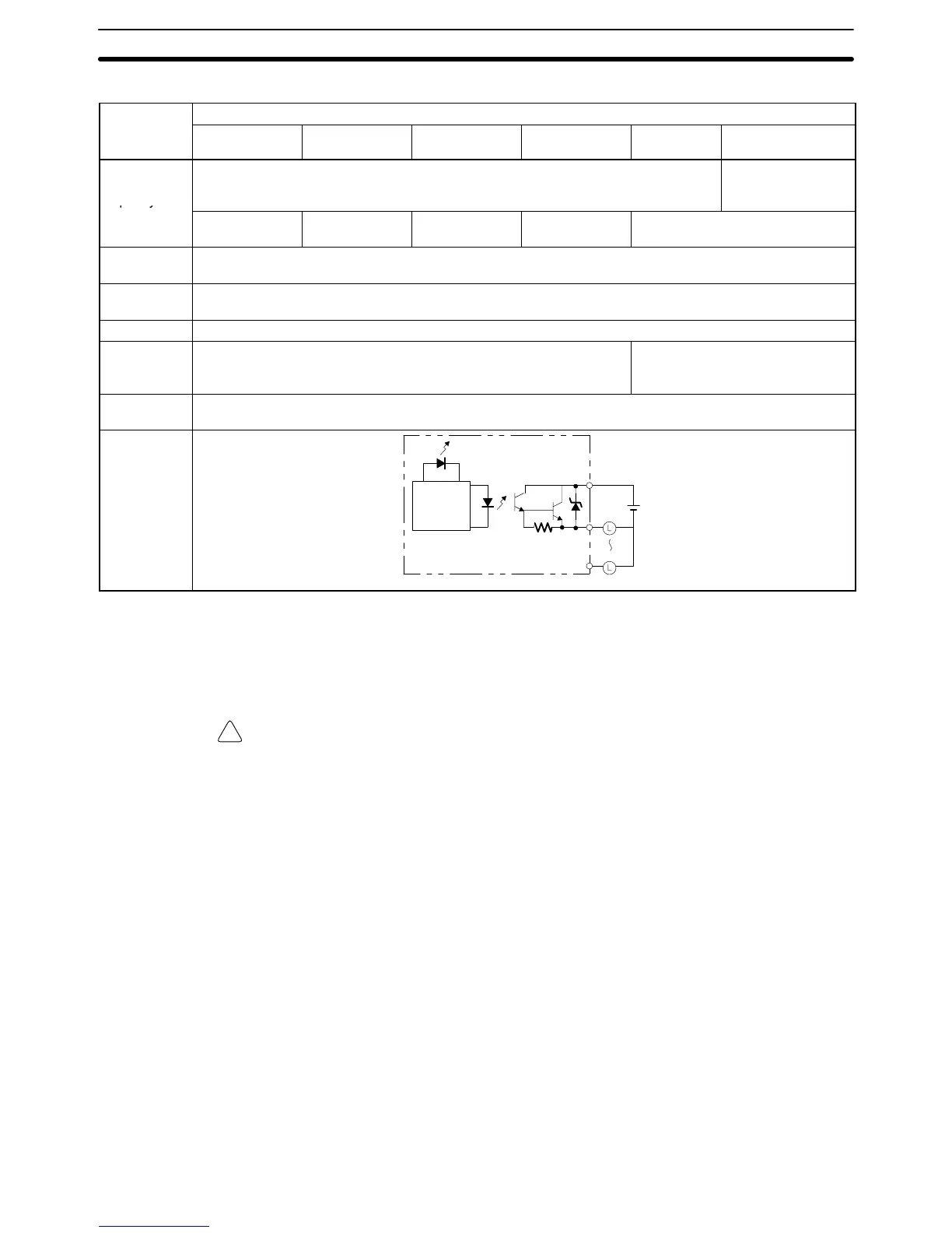
Transistor Outputs (Sourcing)
Item
Specification
CPM1A-
10CDT1-(-V1)
CPM1A-
20CDT1-(-V1)
CPM1A-
30CDT1-(-V1)
CPM1A-
40CDT1-(-V1)
CPM1A-
20EDT1
CPM1A-8ET1
Max.
switching
capacity
24 VDC
+10%
/
–15%
, 0.3 A/point (See note.) 4.5 to 30 VDC
0.2 A (See note 2.)
0.3 A (See note 3.)
0.9 A/Unit 0.9 A/common
1.8 A/Unit
0.9 A/common
2.7 A/Unit
0.9 A/common
3.6 A/Unit
0.9 A/common
1.8 A/Unit
Leakage
current
0.1 mA max.
Residual
voltage
1.5 V max.
ON delay 0.1 ms max.
OFF delay OUT01000/01001: 0.2 ms max. (load current: 100 to 300 mA)
0.5 ms max. (load current: 5 to 100 mA)
Other than OUT01000/01001: 1 ms max. (load current: 5 to 300 mA)
1 ms max.
(24 VDC
+10%
/
–5%
, 5 to 300 mA)
Fuse V1 CPU Units: No fuse
Expansion I/O Units and Pre-V1 CPU Units 1.25 A/common (cannot be replaced by the user)
Circuit
configuration
OUT
COM (+)
Output LED
Internal
Circuits
24 VDC
OUT
Note When using the OUT01000 or OUT01001 as a pulse output, connect dummy
resistors as required to set the load current to 0.1 to 0.2 A. If the load current is
below 0.1 A, the ON-to-OFF response time will become longer and high-speed
pulse will not be output. On the other hand, if the load current is above 0.2 A, the
transistor may generate heat and components may be damaged.
Caution Do not apply voltage in excess of the maximum switching capacity to an output
terminal. It may result in damage to the product or fire.
Specifications Section 2-1