59
Leakage Current (24 VDC) A leakage current can cause false inputs when using 2-wire sensors (proximity
switches or photoelectric switches) or limit switches with LEDs.
False inputs won’t occur if the leakage current is less than 1.0 mA (2.5 mA for
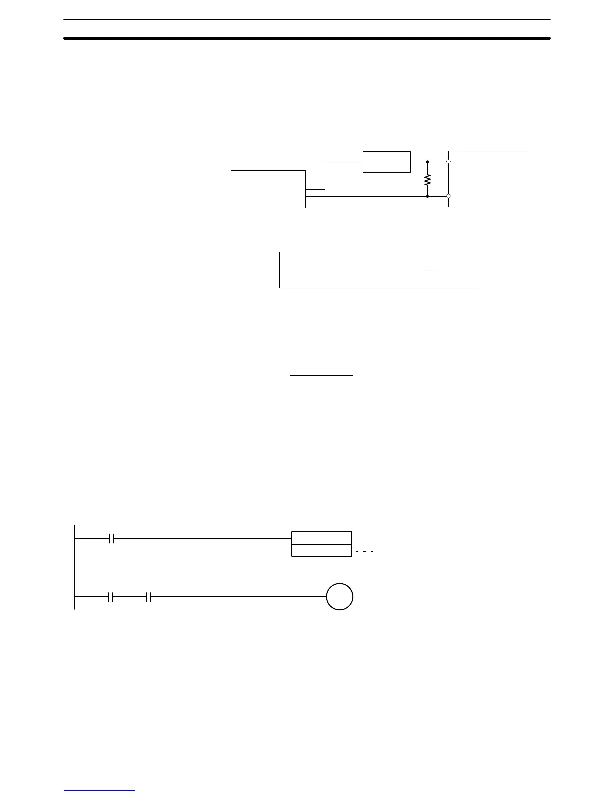
IN00000 to IN00002), but if the leakage current exceeds these values, insert a
bleeder resistor in the circuit to reduce the input impedance, as shown in the fol-
lowing diagram.
R
CPM1A
Input power
supply
Bleeder resistor
2-wire sensor, etc.
I: Device’s leakage current (mA)
R: Bleeder resistance (kΩ)
W: Bleeder resistor’s power rating (W)
The equations above were derived from the following equations:
L
C
: CPM1A’s input impedance (kΩ)
I
C
: CPM1A’s input current (mA)
E
C
: CPM1A’s OFF voltage (V) = 5.0 V
R +
L
C
5.0
I L
C
–5.0
kW max. W +
2.3
R
Wmin.
I
R
Input voltage (24)
Input Current (I
C
)
R )
Input voltage (24)
Input Current (I
C
)
x OFF voltage (E
C
:5.0)
W y
Input voltage (24)
R
Input voltage (24) tolerance (4)
Refer to 2-1-3 I/O Specifications for details on the values L
C
, I
C
, and E
C
.
The input impedance, input current, and OFF voltage may vary depending on the
input being used. (IN00000 through IN00002 have different values.)
Sensor Surge Current If a sensor power supply is turned ON when the PC is ON and ready to receive
inputs, surge current from the sensor may result in an incorrect input. To prevent
improper operation, use the following type of programming in the ladder pro-
gram to delay accepting inputs from a sensor from when the sensor is turned ON
until the sensor reaches stable operation.
00000: Sensor power supply voltage detection
Time required for sensor to stabilize
(for OMRON Proximity Sensor): 100 ms
00001: Input from sensor
TIM 0000
#0002
00000
01000
TIM000 00001
Note The SV of TIM 000 can be set to #0001 (0.1 s) to achieve a delay time of 100 ms,
but the timer accuracy is 0 to 0.1 s, meaning that the timer’s Completion Flag
may turn ON immediately after the timer input. The SV must thus be set to #0002
(0.2 s) or higher to allow for timer accuracy.
Inductive Loads When connecting an inductive load to an input, connect a diode in parallel with
the load. The diode should satisfy the following requirements:
1, 2, 3... 1. Peak reverse-breakdown voltage must be at least 3 times the load voltage.
Wiring and Connections
Section 3-4