9 D6F-series MEMS Flaw Sensor User’s Manual (A286)
5.1.3 Permission pressure performance
When high pressure is impressed into a flow sensor, there is a concern about airproof
degradation. So, the maximum pressure that can be impressed to a flow sensor is defined
as Maximum Permission Pressure.
For example, the maximum permission pressure of D6F-01A1-110 is defined as 200kPa,
this means that airproof specifications and operating characteristic specifications after the
pressure test of 3 minutes at 200kPa are guaranteed.
Airproof is defined as the leak rate when a constant positive pressure is impressed to a flow
sensor. For example, D6F-01A1-110 guarantees that when the positive pressure of 100kPa
is impressed, the leak rate is 1x10
-4
[Pa m3 / s] or less.
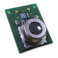
5.1.4 Repeatability
OMRON flow sensors have an excellent repeatability characteristic because they have a
unique flow path design which results in a stable gas flow. The repeatability is not
guaranteed but a reference value.
Fig.6 Repeatability characteristic Fig.7 Flow path design
6 Usage of Flow Sensor
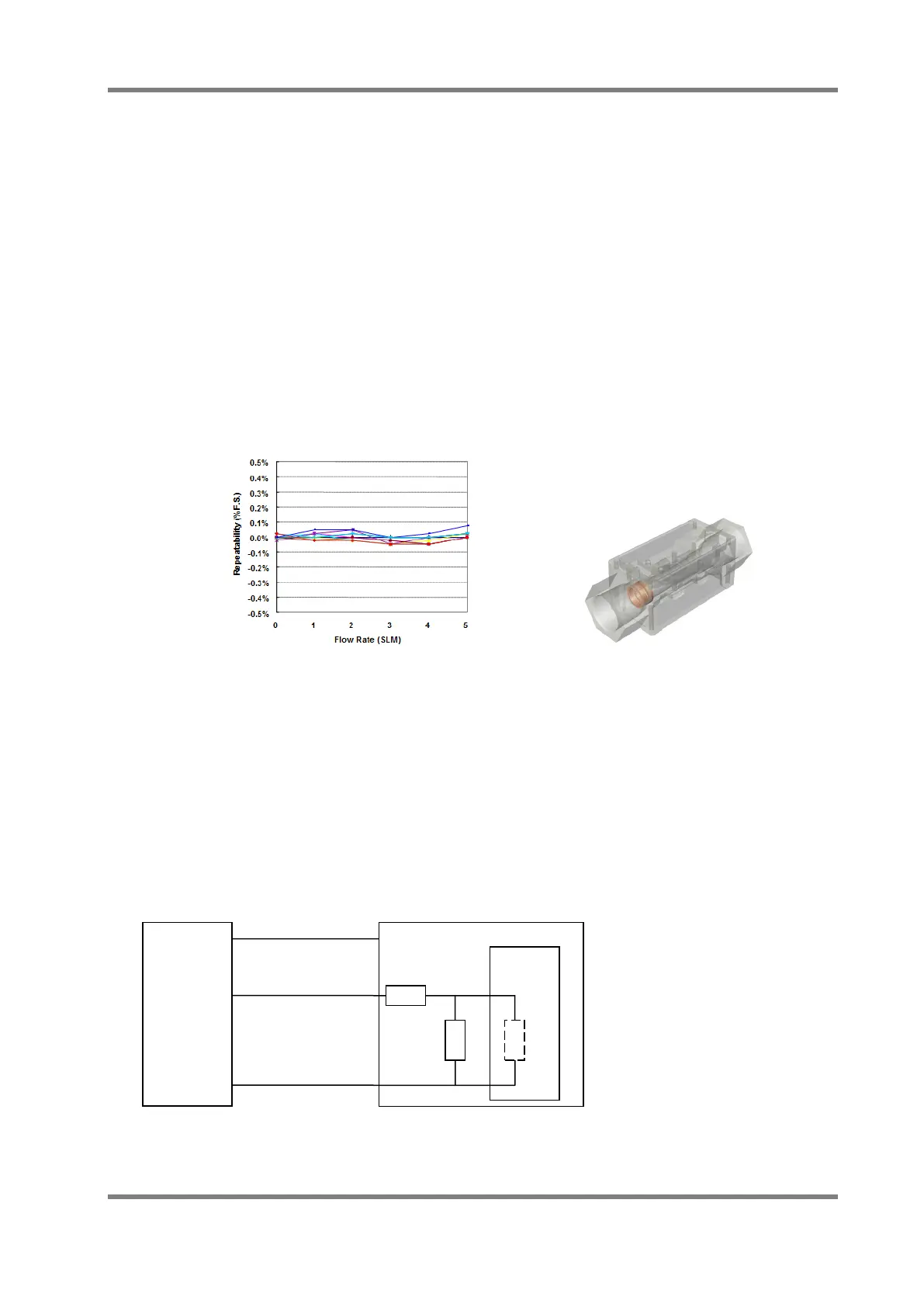
6.1 Electrical Connection
The load resistance (Combined resistance seen from the flow sensor side) between the Vout
and GND terminals of the flow sensor should be 10kΩ or more. However, if you want to connect
a resistor (R1) between the voltage output terminal (Vout) of the flow sensor and the terminal to
detect the voltage (such as ADC input), please be mindful of the voltage drop by resistor (R1). In
general, it is recommended that R1 is less than 1/1000 (Less than 0.1% output voltage drop) of
the parallel resistance of R3 and R2 (R2||R3). Also be sure to check the cable resistance. If the
cable length is long, the resistance of the cable shall be deemed as R1.
Fig.8 Load resistance of the output line
R1
R3
Vout
GND
ADC etc.
Flow
Sensor
Load resistance : R1+R2||R3 > 10kΩ
Voltage drop at R1 : ΔV = Vout×R1/(R1+R2||R3)
 Loading...