D6F-series MEMS Flaw Sensor User’s Manual (A286) 4
Table 2 Outline Specifications of D6F series
Series Name
Flow Rate Type Port Style Features
D6F-□A1 Air 1 ~ 2 lpm Mass Flow Bamboo Joint Compact Size
High Precision
Low Flow Rate
D6F-□N2 City gas*1 1 ~ 5 lpm Mass Flow Rc1/4 Screw Flammable Gas
Metal Body
D6F-02L2 LPG 2 lpm Mass Flow Rc1/4Screw Flammable Gas
Metal Body
D6F-03A Air 3 lpm Mass Flow M5 Screw High Response Time
D6F-□A5 Air 10 ~ 50 lpm Mass Flow Manifold Compact Size
High Flow Rate
D6F-□A6□ Air 10 ~ 50 lpm Mass Flow Rc1/4 Screw
NPT1/8 Screw
Compact Size
High Flow Rate
D6F-□□7 City gas*1
LPG / Air
2 ~ 50 lpm Mass Flow Quick Joint (P10) Quick Joint
D6F-□AB71 Air 30 ~ 70 lpm Mass Flow Quick Joint (P14) Quick Joint
Pulsation Reduction
D6F-P Air 0.1 ~ 1 lpm Mass Flow Bamboo / Manifold DSS*2 / Bidirectional
D6F-W Air 1 ~ 10 m/s Flow Velocity - DSS*2
D6F-V03A1 Air 3 m/s Flow Velocity - Low Cost of D6F-W
D6F-PH Air ±500 Pa Differential
Pressure
Bamboo Joint
Digital Output
Differential Pressure
Note. *1 : City Gas (Natural Gas) Standard:13A, *2 : DSS: Dust Segregation System
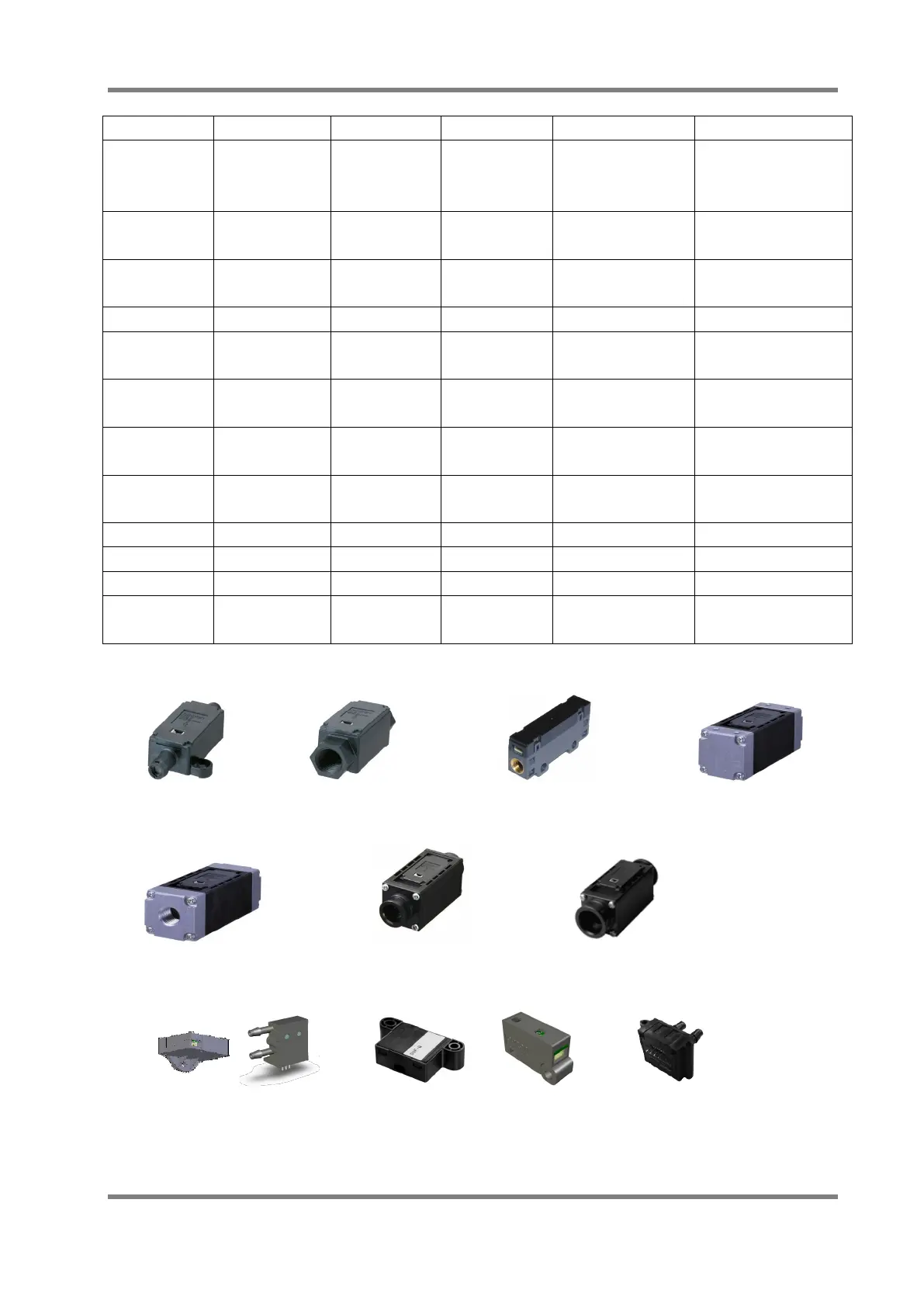
D6F-A1 D6F-□N2/-02L2 D6F-03A D6F-□A5
D6F-□□6 D6F-□□7 D6F-□AB7
D6F-P D6F-W D6F-V03A1 D6F-PH
Fig. 2 D6F Series
4 Operating principle
4.1 Basic structure of MEMS flow sensor chip
The basic structure of a MEMS flow sensor chip is shown in Fig.3. This sensor chip adopts a