5 D6F-series MEMS Flaw Sensor User’s Manual (A286)
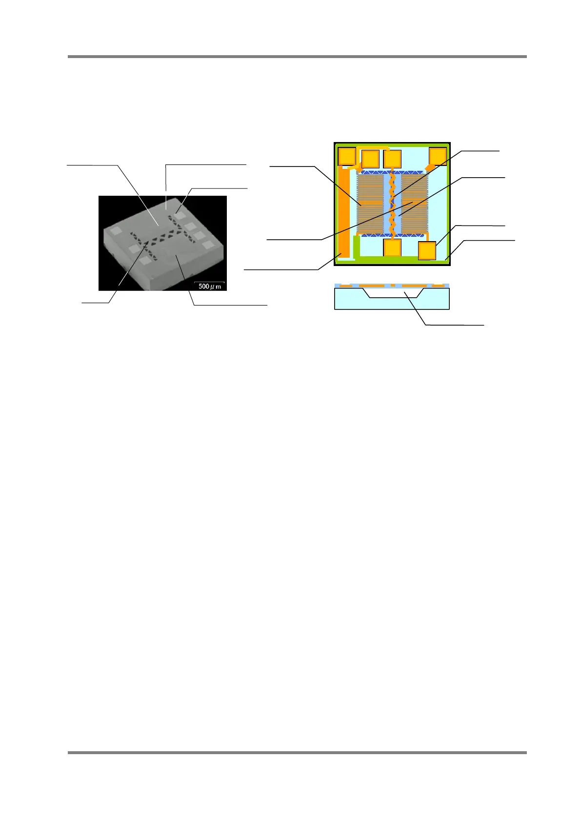
mass flow sensing method by using heat wire. It has a heater in the center of the chip, and the
upstream thermopile (A) and the downstream thermopile (B) are located on either side of the
heater, the base thermo-scope near the thermopile is made by a semiconductor process. The
cavity is formed at the bottom of the heater and the thermopile arrays, so then it is possible to
detect the heat from the heater effectively.
Fig.3. Flow Sensor Chip Structure
Base Thermo-scope
Downstream
Thermopile B
Upstream
Thermopile A
Heater
Thin film
Cavity
Contact pad
Heater
Contact pad
Downstream
Contact Pad
Base thermoscope
Upstream