11 D6F-series MEMS Flaw Sensor User’s Manual (A286)
6.2.3 Manifold mount type
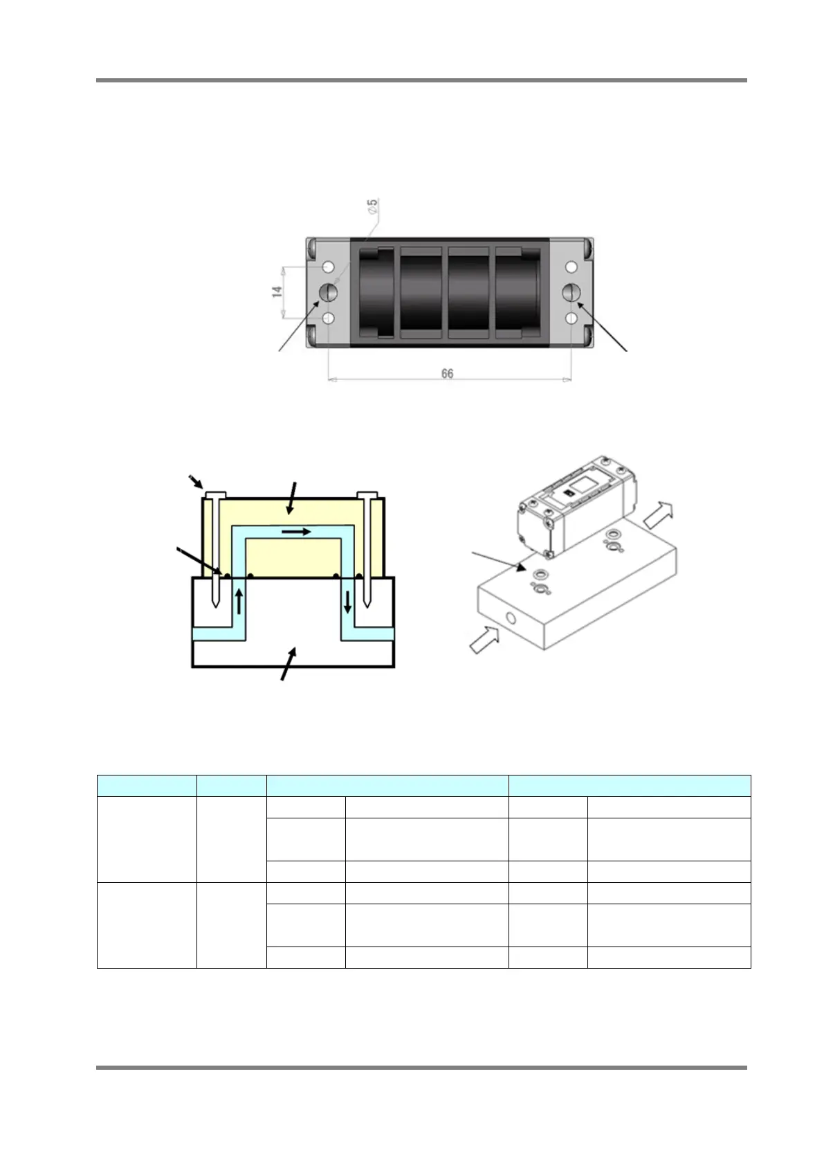
The D6F-□A5 and D6F-P series have a manifold mount type. A manifold mount type, even
if there is no space in the straight pipe direction can be installed in a small space. Below
shows the dimensions of the bottom view and the connection example of the manifold mount
type D6F-□A5.
Inlet
Outlet
Bottom view
Inlet
Outlet
Bottom view
Fig.11 D6F-□A5 Bottom view
O-Ring
Inlet
Outlet
Clamping screw
MEMS Flow sensor (A5 Type)
Gasket/O-Ring
Seal
Manifold block
O-Ring
Inlet
Outlet
Clamping screw
MEMS Flow sensor (A5 Type)
Gasket/O-Ring
Seal
Manifold block
Fig.12 Connection example for manifold mount type
Table 5 Recommended O-ring type
Product Type Port Style Recommended O-Ring Type Reference O-Ring Type
D6F-□□A5
Manifold
Designation JIS B 2401 P5 Designation ISO 3601-1 A0048G
Size
Inner diameter :4.80±0.15mm
Cross section :1.90±0.08mm
Size
Inner diameter : 4.87±0.15mm
Cross section : 1.80±0.08mm
Material NBR (for reference) Material NBR (for reference)
D6F-P□□□□AM
Manifold
Designation JIS B 2401 P4 Designation ISO 3601-1 A0037G
Size
Inner diameter : 3.80±0.14mm
Cross section : 1.90±0.08mm
Size
Inner diameter : 3.75±0.14mm
Cross section : 1.80±0.08mm
Material NBR (for reference) Material NBR (for reference)