333
Appendix
Note (1) Initialized to input setting range upper and lower limits, or scaling upper and lower limits.
(2) Initialized to SP upper and lower limits.
(3) Clamped by SP upper and lower limits.
(4) Initialized only when the input type is changed to analog input when RT turns ON. The defaults are
as follows: RT: OFF
(5) Initialization is performed as shown below according to the transfer output type setting. The initial-
ization differs depending on the changed parameter and the output type setting.
SP: SP upper and lower limits
Ramp SP: SP upper and lower limits
PV: Input setting range upper and lower limits or scaling upper and lower limits
MV (Heating): 100.0/0.0
MV (Cooling): 100.0/0.0
Valve Opening: 100.0/0.0
(5.1) Initialized only when the transfer output type is set to SP, Ramp SP, or PV.
(5.2) Initialized only when the transfer output type is set to MV (Heating) or MV (Cooling).
(5.3) Initialized to the above default values regardless of the settings for changing the transfer output
type.
(6) Initialized as follows according to the Standard or Heating/Cooling parameter setting.
MV Upper Limit: 105.0
MV Lower Limit: Standard −5.0, heating/cooling −105.0
(7) For standard models, initialized to control output (cooling) for heating/cooling control, according to
the following. (The defaults for standard control and for models with position-propotional control are
the defaults in the parameter list.)
With control output 2: The Control Output 2 Assignment parameter is initialized to control output
(cooling).
Without control output 2 and E5CN-H: The Auxiliary Output 2 Assignment parameter is initialized to
control output (cooling).
(8) When the program pattern is OFF, the Auxiliary Output 1 Assignment parameter is initialized to
alarm output 1. When the program pattern is not OFF, the Auxiliary Output 1 Assignment parameter
is initialized to program end output.
(9) When the program pattern is changed to OFF, if the Program Start parameter is assigned it is ini-
tialized to “not assigned.”
(10) If the password is changed, it will be initialized to the new password.
Bank 1 to 7 SP
--- --- --- --- --- ---
Bank 0 to 7 Wait Band
--- --- --- --- --- ---
PID 1 to 8 Proportional Band
(See note 16.)
--- --- --- --- --- ---
PID 1 to 8 Integral Time (See note 16.)
---
● (See note 17.)
--- --- --- ---
PID 1 to 8 Derivative Time
(See note 16.)
--- --- --- --- --- ---
PID 1 to 8 MV Upper Limit,
PID 1 to 8 MV Lower Limit
--- --- --- --- --- ---
PID 1 to 8 Automatic Selection Range
Upper Limit
--- --- ---
● (See note 14.)
--- ---
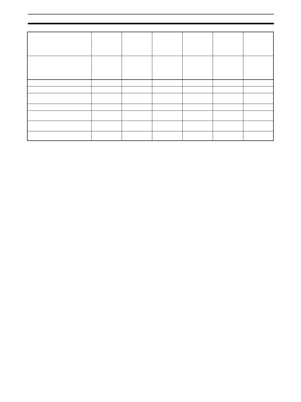
Changed
parameter
Related initialized parameters
Transfer Output
Type
Floating/Closed Bank Numbers
Used
PID Set
Automatic
Selection Data
Direct Setting of
Position
Proportional MV
Password to
Move to Protect
Level
Related parameter initialization
execution condition
--- Models with
position-
proportional
control and FB
input
--- Models with
position-
proportional
control and FB
input, close
control
---

 Loading...


