37
Wiring Terminals Section 2-2
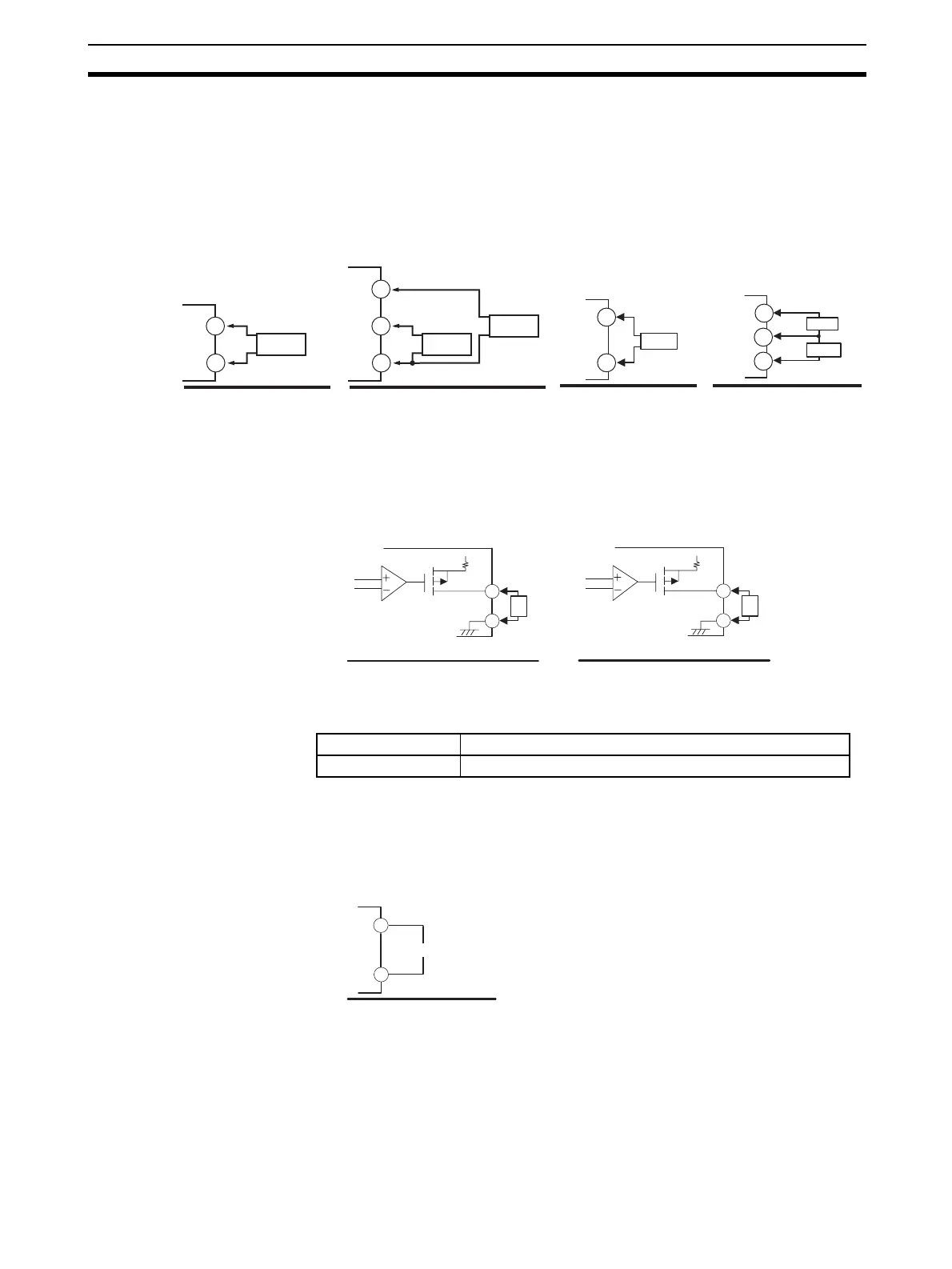
CT Inputs • When the HB alarm, HS alarm, or heater overcurrent alarm is to be used
with the E5CN-H@M@-500 with an E53-CN@H/HH@N2 Option Unit, con-
nect a current transformer (CT) across terminals 14 and 15 or terminals
13 and 15 (no polarity).
• When the HB alarm, HS alarm, or heater overcurrent alarm is to be used
with the E5AN/EN-H@@H@-500 or E5AN/EN-H@@HH@-500, connect a
current transformer (CT) across terminals 14 and 15 or terminals 15 and
16 (no polarity).
Transfer Output • On the E5CN-H@M@-500 with an E53-CN@FN2, the transfer output is
output across terminals 14 and 15.
• On the E5AN/EN-H@@F-500, transfer output is output across terminals
27 and 28.
Even with models that do not have a transfer output, control outputs 1 or 2 can
be used as a simple transfer output if it is a current output or linear output. For
details on the operation, refer to 4-14 Using the Transfer Output.
Remote SP Input • The E5AN-H and E5EN-H support remote SP inputs. To use remote SP,
connect to terminals 29 and 30.
Remote SP inputs are not electrically isolated from the internal circuits. When
using a grounding thermocouple, do not connect any of the remote SP input
terminals to the ground. (If a remote SP input terminal is connected to the
ground, errors will occur in the measured temperature as a result of leakage
current.)
E53-CN@H@N2
(for E5CN-H)
15
14
CT
E53-CN@HH@N2
15
14
13
CT1
CT2
CT
E5AN/EN-H@@H@-500 E5AN/EN-H@@HH@-500
CT2
CT1
14
15
14
15
16
Output type Specifications
Current 4 to 20 mA DC, Load: 600 Ω max., Resolution: 10,000
L
+
v
+
−
27
28
L
+
v
+
−
14
15
Current
Current
E53-CN@FN2
for E5CN-H
E5AN/EN-H@@F-500
29
30
+
−
4 to 20 mA
E5AN/EN-H
 Loading...


